
Metrology definition
State the point of interest, measurement line, reference temperature, operating states and whether position follows the scale, stage or workpiece.
TECHNOLOGY / PRECISION STAGE METROLOGY
Build a linear encoder thermal error budget for precision stages by comparing scale CTE, mounting, sensors, compensation and acceptance evidence.
Published
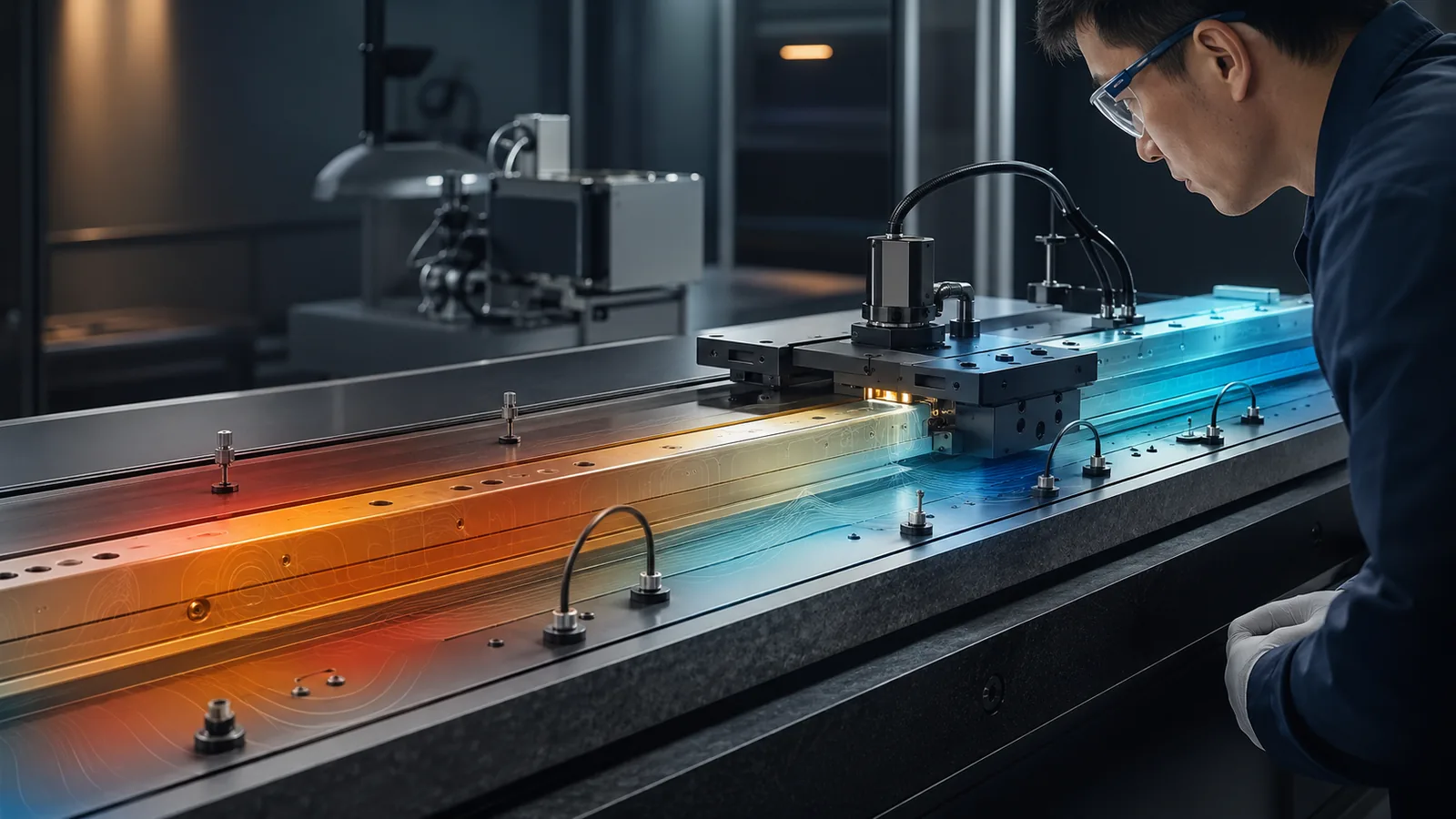
DIRECT ANSWER
A linear encoder thermal error budget should define the reported position at a reference temperature, identify what length the encoder scale represents, and model how the scale, machine substrate and workpiece move as temperature changes. The first-order scale term is the coefficient of thermal expansion multiplied by the active length and temperature change, but mounting constraint, gradients, sensor location, warm-up and Abbe offset can make the real axis behavior different from that simple calculation.
Do not choose a scale only because its nominal expansion coefficient is small. Decide whether the measurement should follow the scale, the stage structure or the workpiece; establish a thermal datum; measure temperatures that represent those bodies; and validate the compensation over the intended operating cycle. Request configuration-specific scale material, mounting instructions, accuracy conditions, temperature data and calibration evidence before releasing the encoder for an OEM design.
ENGINEERING CONTEXT
Semiconductor, photonics and metrology stages can report nanometer-scale increments while drifting by micrometers as the scale, structure and process load change temperature. The buyer must convert thermal behavior into an axis-level error budget and an executable acceptance test rather than treating room temperature or scale material as a catalogue checkbox.
Discuss your requirement ↗CRITICAL REQUIREMENTS
State the point of interest, measurement line, reference temperature, operating states and whether position follows the scale, stage or workpiece.
Define scale and substrate materials, mounting constraint, thermal datum, heat sources, gradients, sensor locations and warm-up behavior.
Test uncorrected and corrected position over representative temperature cycles with a traceable reference and stated uncertainty.
BUYER MATRIX
Give every shortlisted supplier the same process definition and request configuration-specific proof.
| Decision | Evidence to obtain | Risk if left open |
|---|---|---|
| Reference state | Reference temperature, coordinate definition and machine operating state | Acceptance results cannot be compared |
| Scale behavior | Material, CTE with source and condition, active length and accuracy condition | Expansion is mistaken for fixed scale accuracy |
| Mounting | Controlled drawing, thermal datum, adhesive or clamp method and substrate material | Installed scale does not follow the assumed model |
| Temperature sensing | Sensor type, calibration, location, contact method, sampling and latency | Measured temperature does not represent the scale |
| Compensation | Equation, coefficients, coordinate sign, limits, update logic and software revision | Correction adds bias or becomes invalid during transients |
| Acceptance | Thermal cycle, reference metrology, uncertainty, residual map and pass rule | A room-temperature point test hides operating drift |
Start the thermal budget at the process point, not at the encoder connector. A wafer-stage axis, mask aligner, inspection gantry or photonics assembly station ultimately controls the location of a chuck, optic, probe or workpiece. Record that point of interest, the direction of measurement and the location of the encoder scale relative to it. If the measurement line is offset from the process point, angular motion can become a linear position error. NIST dimensional-metrology material describes this Abbe error as the product of the perpendicular offset and the sine of the angular error.
Next define the coordinate being reported. Is the machine expected to reproduce a physical location at its operating temperature, report a dimension normalized to a reference temperature, or follow a thermally expanding workpiece? Those are different measurands. ISO 1:2022 defines the concepts of reference temperature and standard reference temperature for geometrical and dimensional properties, including the measurand used for verification or calibration. The OEM requirement should name the reference rather than assuming every controller, drawing and calibration file uses the same convention.
Divide the duty cycle into states: cold start, warm-up, idle, production motion, process heating, maintenance restart and any vacuum bake or chamber recovery that affects the axis. For each state, identify the allowed position error and the time at which it applies. This avoids an impossible specification such as demanding a fully stabilized result immediately after power-up while also accepting hardware that requires a thermal settling period.
For an initial estimate, use change in length equals CTE multiplied by active length and temperature change. Keep the units visible. If a scale has a coefficient of 10 micrometers per meter per degree Celsius, a one-meter active length changing by 2 °C changes length by about 20 micrometers under the assumed free-expansion model. This is a sensitivity calculation, not an accuracy claim and not necessarily the final machine error.
NIST identifies the thermal expansion coefficient of an artifact as one of the two largest uncertainty sources in its highest-accuracy length measurements. Its dimensional-metrology guidance also shows that a measurement made away from 20 °C requires a thermal-expansion correction and that uncertainty in the assumed coefficient contributes to measurement uncertainty. The buyer therefore needs the coefficient's source, applicable temperature range and uncertainty or tolerance where available, not only a material name copied into an RFQ.
Run the estimate at the full active length and at important positions relative to the thermal datum. Include the scale, structural metrology loop and workpiece where each affects the reported process coordinate. Use worst credible temperatures for early risk screening, then replace them with measured distributions and time histories from the prototype. A single ambient reading cannot represent a scale exposed to motor heat, bearings, illumination, electronics, process gas or a temperature-controlled chuck.
Document whether the coefficient is constant, whether expansion is uniform, where zero position is anchored and whether the scale is free, constrained or made to follow the substrate. Record sign conventions and coordinate direction. These notes allow controls, mechanical and metrology engineers to implement the same correction rather than producing three mathematically valid but incompatible models.
Scale material does not determine installed thermal behavior by itself. A scale that can expand from a defined datum behaves differently from a scale bonded or clamped so that the machine substrate influences its length. Adhesive thickness and compliance, end clamps, fastener locations, guide features and the distance from the datum to the read point all affect the mechanical boundary condition. Ask the encoder supplier for the approved installation method and do not substitute a convenient adhesive or clamp without reviewing the metrology consequence.
Choose the thermal reference that best supports the process. A low-expansion scale can help when the desired coordinate should remain stable despite structural temperature change. A scale intentionally made to follow the substrate may be more appropriate when the process coordinate should track that structure. A scale with a well-characterized coefficient can also support active compensation when its temperature is measured adequately. None of these architectures is universally superior; the correct one minimizes uncertainty between the encoder coordinate and the actual point of interest.
SENFU's source-backed SMG20 data identify stainless-steel and glass scale routes. The documented steel-scale coefficient is 10.2 µm/m/°C and the glass-scale coefficient is 8 µm/m/°C; its published scale accuracy is stated at 20 °C. Those values support a preliminary comparison only. The ordered scale length, mounting drawing, material route, readhead configuration and application temperature still need to be fixed in the technical package before the OEM assigns a thermal error limit.
A stable room does not guarantee a uniform axis. Linear motors, voice coils, bearings, cable carriers, amplifiers, cameras, illumination and process hardware can create local heat. In air, convection and airflow influence the temperature field; in vacuum, convection is absent and heat must move through conduction and radiation paths. The scale, substrate and workpiece can therefore reach different temperatures and settle at different rates even when the chamber or room sensor appears stable.
Create a thermal map during the representative motion recipe. Place temporary sensors near the scale datum, along the scale, on the structural loop and at the workpiece or chuck. Log position residual, motor current, coolant state, ambient or chamber temperature and elapsed time on the same clock. The objective is to identify which measured temperatures explain position change and where a gradient or lag makes a one-sensor model inadequate.
Pay attention to transients. NIST work on thermally expanding slender measurement structures shows that temperature-driven length error depends on position and time when heating and cooling are nonuniform. A compensation model derived only after full soak may work well at equilibrium and fail during production start, recipe changes or pauses. Define a warm-up sequence or state-dependent correction if the residual cannot be kept within budget across all relevant states.
A temperature channel is useful only when its reading represents the body used in the correction model. Specify the sensor type, calibration status, uncertainty, mounting contact, thermal mass, cable heat path, sampling interval and controller conversion. Check self-heating and electromagnetic noise near motors or high-voltage equipment. For a long axis or strong local heat source, multiple sensors may be needed to estimate a gradient rather than one average temperature.
Locate sensors through correlation testing. A sensor attached to the stage casting may be mechanically convenient but lag the thin scale; a nearby air sensor may respond quickly while missing the substrate temperature; a chuck sensor may represent the workpiece but not the encoder reference. Compare each channel against position residual through heating and cooling cycles. Select inputs because they predict the metrology error with stable residuals, not because they are easiest to wire.
Keep the measurement chain auditable. Record sensor serial or channel identity, calibration date, conversion coefficients, software revision and replacement rule. If a controller uses a nominal coefficient, state its value and units in the released configuration. Changing a sensor location, adhesive pad, filter constant or averaging window can change the compensation even when the encoder itself is unchanged, so these fields belong in change control.
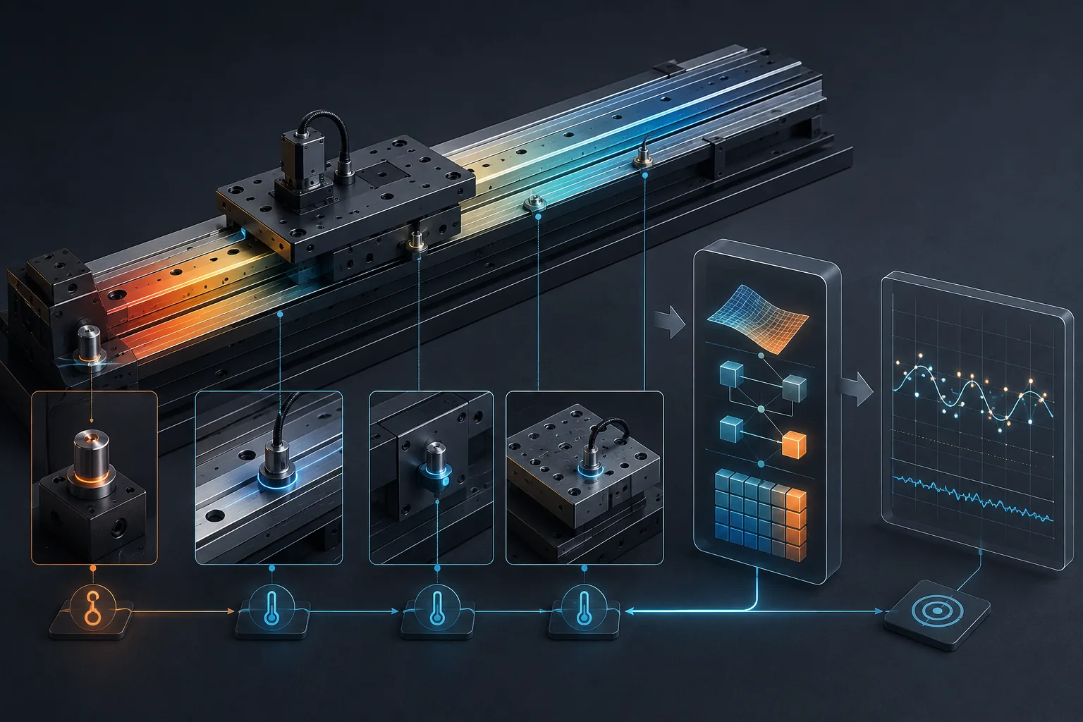
Preserve both uncompensated and compensated position data. The raw map reveals whether the hardware and environment are stable; the corrected map shows whether the model reduces the intended error. A simple coefficient-based correction may be adequate for uniform scale expansion. A position-dependent map may be needed when scale calibration and thermal behavior vary along travel. A state or time term may be necessary when warm-up creates repeatable lag, but model complexity should be justified by independent validation data.
Do not let the compensation absorb unrelated errors. Scale calibration, interpolation error, straightness, pitch, yaw, Abbe offset, stage repeatability and reference-instrument uncertainty should remain identifiable in the budget. If the model is trained against one reference trajectory, test it on different positions, directions, speeds and thermal cycles. Otherwise it may fit the commissioning data without predicting the operating machine.
Controls requirements should include coefficient storage, units, sign, update rate, valid temperature and position range, startup behavior, sensor-fault response and version control. Decide whether motion is inhibited, derated or allowed with a diagnostic when a temperature input is missing or implausible. The safety strategy and process risk determine that response; the encoder supplier should not invent it. Preserve the released parameters with the machine calibration record.
Write the verification protocol before final supplier selection. Define the axis configuration, reference instrument, setup geometry, Abbe offset, environmental sensors, positions, dwell, motion recipe, heating and cooling sequence, sample interval, repeat count and acceptance calculation. The test should include the operating states that drive the budget, not only a single point after overnight stabilization. If the machine will use compensation, test both the raw behavior and the released correction.
Connect the reference result to a documented calibration chain and include measurement uncertainty in the decision. NIST explains that metrological traceability requires an unbroken chain of calibrations in which each step contributes to uncertainty; traceability alone does not prove the uncertainty is small enough for the intended acceptance limit. State the decision rule for results near the tolerance and identify how an inconclusive result will be handled.
Review residual error by position, temperature, time, direction and machine state. A single maximum value can hide a repeatable slope, local distortion, hysteresis or warm-up lag that points to a correctable cause. Preserve raw data, analysis code or workbook, sensor records, software parameters and the exact encoder configuration. This package becomes the baseline for production release, service recalibration and any later hardware or software change.
A useful RFQ gives every encoder supplier the same axis definition. Include travel, process point, measurement line, error budget, reference temperature, duty cycle, maximum speed, heat sources, environment, scale support material, proposed mounting, controller, cable route and planned temperature sensing. Mark which values are confirmed and which need application engineering. Ask the supplier to identify the exact readhead, scale, length, material, mounting parts, drawing revisions and limits used in its response.
Request the scale accuracy condition separately from thermal data. Obtain material and CTE information with the source and applicable range; approved mounting and datum instructions; operating and storage limits; sensor or compensation requirements; and configuration-specific installation drawings. Ask which claims are guaranteed, typical, calculated or subject to confirmation. Do not convert a family-level statement into a production acceptance value.
For SENFU evaluation, the SMG20 and SMG26 routes both publish steel and glass scale options and scale accuracy at 20 °C, while exact configuration closure remains necessary. SAG21 provides an absolute BiSS-C route when startup position behavior is part of the architecture decision. The correct shortlist follows the motion profile, interface, envelope and thermal model together; thermal performance cannot be ranked from material or resolution alone.
CONCLUSION
A defensible linear encoder thermal error budget links the process coordinate to a reference temperature, scale material, mounting boundary, heat map, temperature measurement and compensation model. It keeps thermal expansion separate from scale accuracy and geometric error, then verifies the combined axis with traceable metrology over the real operating cycle.
For a SENFU technical review, send the stage drawing, travel, measurement line, scale support material, expected temperature range and gradients, motion recipe, controller interface, target error budget and proposed acceptance method. SENFU can use that package to identify an encoder configuration route and the scale, mounting and validation evidence that must be closed before an OEM release.
SOLUTION ROUTES
EVIDENCE CHECKLIST
FAQ
For a first-order estimate, multiply the scale coefficient of thermal expansion by active length and temperature change. Then add uncertainty in the coefficient and temperature, mounting effects, gradients, geometric offsets and other axis errors. Validate the model because an installed, constrained scale may not behave like a freely expanding material.
No. It helps when the desired coordinate should remain stable against temperature, but another application may need the encoder coordinate to follow the machine substrate or workpiece. Mounting, thermal datum, sensor quality and compensation determine whether the scale behavior matches the actual measurand.
Place sensors where their readings represent the scale, structure and workpiece used in the error model. Confirm locations by correlating each temperature channel with position residual during representative heating and cooling cycles. A room sensor alone is rarely enough when local heat sources or gradients are significant.
A value stated at 20 °C describes the published condition, not the complete axis at every temperature. The buyer should model scale expansion, mounting and machine geometry at the operating condition and request any configuration-specific accuracy or calibration evidence needed outside the stated condition.
Use a documented, traceable reference setup and test raw and compensated position over representative positions, directions, duty cycles and temperature transitions. Include sensor calibration, reference uncertainty, model revision and a decision rule. Reserve independent cycles for validation rather than evaluating only the data used to fit the model.
Send travel, required position error, process point, measurement line, scale support material, temperature range and gradients, heat sources, warm-up requirement, environment, motion profile, controller interface, proposed sensor locations and acceptance method. Include drawings and any measured thermal data available.
AUTHORITATIVE SOURCES
TECHNICAL REVIEW
Send the application, critical parameters and any drawing or process information available.
Discuss your application ↗