
Configuration identity
Fix model, scale, readhead, resolution, output, cable, connector, environment option, firmware where relevant and drawing revision.
TECHNOLOGY / EUROPEAN OEM PROCUREMENT
A practical European OEM checklist for qualifying optical encoder suppliers, technical data, test evidence, EMC records, traceability and change control.
Published

DIRECT ANSWER
European OEMs should qualify an optical encoder supplier at three levels: the exact ordered configuration, the evidence behind the stated performance, and the supplier's ability to preserve that configuration through production and change control. A generic catalogue, an attractive resolution value or a certificate for a related model is not enough.
Start with a controlled requirement sheet covering motion, interface, mechanics and environment. Then request model- and configuration-specific drawings, electrical timing, test conditions, calibration or inspection evidence, compliance scope, revision status and notification rules. The machine manufacturer or importer should separately determine which EU laws and conformity obligations apply to the finished product and to each component; a supplier document supports that assessment but does not replace it.
ENGINEERING CONTEXT
Encoder procurement becomes risky when commercial naming, mechanical drawings, signal configuration, test evidence and compliance documents do not identify the same deliverable. The qualification task is to create a traceable chain from the OEM requirement to the ordering code, evidence package, incoming inspection and approved production revision.
Discuss your requirement ↗CRITICAL REQUIREMENTS
Fix model, scale, readhead, resolution, output, cable, connector, environment option, firmware where relevant and drawing revision.
Connect each critical claim to a stated test method, conditions, sample configuration, result, uncertainty or tolerance, and document revision.
Agree on change notification, nonconformance handling, traceability, replacement compatibility and the records needed at incoming inspection.
BUYER MATRIX
Give every shortlisted supplier the same process definition and request configuration-specific proof.
| Qualification gate | Evidence to request | Buyer decision |
|---|---|---|
| Product identity | Ordering code, configuration matrix, controlled drawing and revision | Can purchasing and engineering identify the same deliverable? |
| Technical fit | Resolution, accuracy, speed, output and environmental data with conditions | Does the selected configuration meet the axis requirement? |
| Integration | Mechanical tolerances, scale mounting, cable, connector and interface timing | Can the OEM design and verify the installation? |
| Validation | Test method, result, measurement uncertainty or tolerance and traceable equipment | Is the evidence adequate for the acceptance decision? |
| Compliance and lifecycle | Applicable declarations, model scope, revision control and change-notification process | Can the configuration remain controlled through production? |
Supplier qualification should begin with the axis, not with a certificate request. Record whether the encoder is a component incorporated into a machine, an apparatus supplied independently, or part of a larger fixed installation. Describe the intended use, target markets and the party that will place the final product on the European market. Those facts affect the regulatory analysis, the evidence the OEM needs from the component supplier and the responsibilities retained by the machine manufacturer or importer.
The European Commission's Blue Guide explains the New Legislative Framework used across EU product rules, while the applicable sector legislation establishes the actual obligations. Under the EMC Directive, for example, a manufacturer placing apparatus on the market must prepare technical documentation, complete the relevant conformity assessment, draw up an EU declaration of conformity when compliance is demonstrated and preserve specified records. That does not mean every encoder configuration automatically carries the same legal status. The buyer should document its applicability decision rather than infer it from a logo, test-report cover or reseller statement.
Create two linked checklists. The first is the machine-level legal and risk assessment owned by the responsible economic operator. The second is the component evidence requested from the encoder supplier. A component test report, declaration or certificate can inform the first checklist only when its model, interface, cable, operating mode and test conditions match the configuration being integrated.
An encoder model name rarely identifies every variable that affects integration. The approved record should include readhead variant, scale material and length, reference-mark arrangement, interpolation or resolution option, output format, supply voltage, cable type and length, connector, vacuum or other environmental option, and any controller or interface unit. Add the supplier drawing number, data-sheet revision and ordering-code definition. If a field is not yet confirmed, label it open rather than allowing sales shorthand to become an engineering requirement.
This configuration baseline prevents three common procurement failures. First, performance evidence from the fastest or lowest-resolution variant is applied to a different ordered option. Second, a compliance record for one interface or control unit is generalized to an entire product family. Third, a mechanically compatible replacement introduces a different electrical, material or cable construction without a new risk review. A signed configuration matrix is more useful than a folder of unrelated PDFs because it shows which evidence belongs to which item.
SENFU's public product records already separate source-backed fields from configuration-dependent notes. European buyers evaluating miniature incremental feedback can compare the documented SMG20 route, the higher-speed SMG26 architecture, the absolute BiSS-C SAG21 route and the compact MICRON-P2 option. The published values are a starting point; the quotation and approved technical package should close every configuration field required by the application.
Give every shortlisted supplier the same requirement sheet. For each item, state the required value, operating condition, acceptance method and whether it is mandatory, preferred or informative. The supplier should answer with the offered configuration, source document and any deviation. This turns a catalogue comparison into a controlled engineering review and exposes assumptions early enough to change the design or request a test.
For a linear axis, include travel, maximum and normal speed, acceleration, required feedback resolution, allowable position error, repeatability target, controller input, supply, cable route, available readhead envelope, scale-mounting concept, temperature range, contamination or vacuum conditions, and service-access constraints. For rotary feedback, add disc geometry, line count, shaft or hub arrangement, eccentricity and angular error budget. Separate the encoder requirement from the complete axis target so that a system-level positioning claim is not assigned to one component.
The response should distinguish guaranteed limits, typical observations and options requiring confirmation. Ask where a value was measured, on how many units, with which scale length or disc, at what temperature and speed, and using which signal-processing configuration. If a statement cannot be connected to a controlled source or an agreed acceptance test, treat it as an open risk rather than converting it into a purchase specification.
Resolution is the smallest reported position increment; it is not proof of accuracy, repeatability or machine positioning performance. A defensible evidence package keeps scale accuracy, interpolation error, repeatability, thermal behavior and test uncertainty separate. The OEM error budget then adds mounting alignment, Abbe offset, structural motion, stage geometry, temperature and controller behavior. This is why a very small digital increment can coexist with a much larger system error.
Dynamic qualification asks a different set of questions. For an incremental encoder, convert the required speed and scale or signal pitch into the expected output frequency, then check the selected interpolation, receiver bandwidth, cable length, termination and controller counting limit. For an absolute interface, confirm clocking, frame timing, position-update behavior, error handling and startup validity. Test at the cable, connector, supply and electromagnetic conditions representative of the machine rather than at an unspecified laboratory default.
Calibration and verification should also be named correctly. The international metrology vocabulary defines metrological traceability through a documented, unbroken calibration chain in which each calibration contributes to uncertainty; it also notes that traceability does not by itself prove that uncertainty is adequate for the intended purpose. Ask for the measurand, method, reference, environmental conditions, result, uncertainty where applicable and decision rule. A calibration statement without scope or uncertainty cannot close a tight acceptance limit.
An optical encoder becomes a measuring system only after the scale, readhead, mechanics, electronics and controller are integrated. Request drawings that define the sensing gap, yaw, pitch and roll tolerances, scale datum, reference-mark location, fastener or adhesive assumptions, cable bend and service envelope. Verify that the tolerances are achievable in production, not only on a carefully adjusted prototype. The incoming inspection plan should identify the dimensions and electrical checks that protect those assumptions.
The scale mounting and measurement line deserve explicit review. Thermal expansion can change indicated position over travel, and an offset between the measurement axis and point of interest converts angular motion into linear error. A supplier does not need to own the entire machine error budget, but it should provide the scale material, mounting method and relevant dimensional data needed for the OEM to calculate those contributions. The OEM should document the datum strategy and the conditions used for any compensation.
Environmental labels require the same discipline. For vacuum use, specify pressure range, process gas, bakeout, material restrictions, cable and connector, heat path and contamination controls. Request configuration-specific material and outgassing evidence where the process requires it. Do not translate a generic 'vacuum compatible' statement into an ultrahigh-vacuum claim. For ordinary industrial environments, still review temperature, humidity, ingress exposure, contamination, vibration, cable flex and grounding against the intended installation.
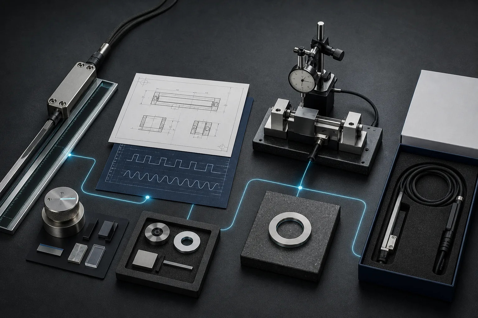
A compliance document should answer five questions: who issued or signed it, which legal requirement or standard it addresses, which exact product and configurations it covers, which evidence supports the conclusion, and which revision or date controls it. Confirm that model identifiers on the declaration, report, certificate, label, quotation and drawing are consistent. If an interface unit, cable or power supply is part of the tested configuration, record it rather than assuming any substitute is equivalent.
The EMC Directive requires an assessment that considers normal intended operating conditions and, where apparatus has multiple configurations, representative configurations identified by the manufacturer. Its technical-documentation provisions cover design, manufacture and operation to the extent needed for assessment. For an OEM, this makes configuration mapping and intended-use evidence operationally important: a report title alone does not demonstrate that the integrated machine, cable routing and installation meet the finished-product obligations.
CE marking is not a third-party quality award and should not be used as a proxy for encoder accuracy. The responsible manufacturer determines applicable EU legislation, carries out the required conformity assessment, compiles technical documentation and signs the EU declaration of conformity where required. Importers and distributors have their own obligations under applicable legislation. Buyers should obtain legal or conformity expertise for their specific product and market rather than relying on a component supplier article as legal advice.
The most useful supplier trial reproduces the intended configuration and the risk-driving conditions. Agree on the sample identity, scale length, mounting, controller, cable, speed profile, temperature, data filtering, reference instrument, warm-up, repeat count and acceptance calculation before testing. Preserve raw data and configuration files. If the test is performed by an external laboratory, verify that its accredited scope covers the relevant measurement and that the reported uncertainty is suitable for the decision.
Metrological traceability is a property of a measurement result, not a decorative phrase attached to an organization. ILAC policy describes an unbroken chain of calibrations to stated references with stated uncertainties, while its calibration-uncertainty policy addresses how uncertainty is estimated and reported. For supplier qualification, the practical question is whether the reported result, traceability chain and uncertainty support the particular tolerance being accepted.
Use guard bands or another documented decision rule when uncertainty is material to a pass/fail limit. Define what happens to an inconclusive result and who approves deviations. The first-article or supplier-approval test can then become the basis for incoming inspection, periodic requalification and failure investigation instead of remaining a one-off demonstration that cannot be reproduced.
Technical approval is incomplete until procurement can preserve the evaluated product. Put the approved ordering code, document set and revision status into the purchase specification. Define which changes require prior notification: optical or electronic design, scale material, cable, connector, firmware, manufacturing location, critical process, sub-supplier or test method. Agree on notification timing and the evidence required for requalification without inventing a universal period that may not fit the supply agreement.
Also clarify nonconformance handling, failure-analysis inputs, return authorization, replacement compatibility, repair or calibration route, record retention and end-of-life communication. Ask who provides application engineering across European working hours, which documents can be supplied in the required language, and how controlled revisions are distributed. These questions are commercial because they affect downtime and engineering effort, but they must remain connected to the technical configuration.
A strong RFQ package lets the supplier respond precisely. Send the requirement-to-evidence matrix, interface and mechanical constraints, environmental definition, target quantities, validation plan and required compliance documents. SENFU can review the source-backed encoder routes, identify open configuration questions and coordinate model-specific documentation without turning unverified statements into guarantees.
CONCLUSION
Optical encoder supplier qualification is successful when engineering, quality and procurement can identify exactly what is being bought, why it meets the axis requirement, how that conclusion was measured and how the approved configuration will remain controlled. The essential output is a traceable requirement-to-evidence record, not the largest collection of brochures.
For a SENFU review, provide the motion profile, feedback architecture, resolution and error budget, controller interface, travel, mechanical envelope, scale mounting, cable, environment, applicable documentation list and planned acceptance test. SENFU can map those inputs to source-backed product data, flag evidence that remains configuration-dependent and prepare the technical questions needed before an RFQ or sample evaluation.
SOLUTION ROUTES
EVIDENCE CHECKLIST
FAQ
Request a controlled data sheet, configuration and ordering-code matrix, mechanical drawing, electrical interface and timing information, installation instructions, performance evidence with conditions, applicable model-scoped compliance records, validation or calibration information where required, and change-control terms.
No. CE marking relates to applicable EU product legislation and conformity responsibilities; it is not an accuracy grade. Accuracy suitability must be established from configuration-specific metrology, installation effects and the complete machine error budget.
Do not assume that scope transfers. Compare the exact model, interface, cable, power arrangement, operating modes, standards, report or certificate scope and revision. Any equivalence decision should be documented by the responsible manufacturer using adequate technical evidence.
Calibration establishes the relationship between indications and reference values with associated uncertainty. Verification confirms that specified requirements are met. Machine acceptance applies agreed tests and decision rules to the integrated system. One activity does not automatically replace the others.
Use the offered configuration, representative scale length and cable, intended controller or receiver, realistic mounting and environmental conditions, the required speed profile, a controlled reference method, repeated runs, raw data, an uncertainty statement where applicable and a pre-agreed acceptance rule.
AUTHORITATIVE SOURCES
TECHNICAL REVIEW
Send the application, critical parameters and any drawing or process information available.
Discuss your application ↗