
Working distance set per sample
Focus adjusted to the actual substrate height, including chuck stack and thickness variation, before any exposure.
TECHNOLOGY / ELECTRON BEAM LITHOGRAPHY
Critical dimension in electron beam lithography is set as much by column condition as by the pattern data. This guide explains how focus, stigmator and beam-position calibration work, which drift contributors matter, and how to build a repeatable calibration routine that keeps linewidths inside specification.
Published

DIRECT ANSWER
Focus and stigmator calibration in electron beam lithography aligns the electron-optical column so that the beam spot is small, round and correctly positioned on the substrate. The routine typically sets the working distance, minimizes astigmatism with the stigmator coils using a stigmation target, verifies spot size against a resolution standard, and checks beam-position offsets against alignment marks—all before the first patterned exposure.
Calibration is repeated at a defined cadence because the column drifts: gun emission changes with filament age and vacuum, lens currents and stage temperature shift over hours, and every new sample height changes the working distance. A documented routine—same targets, same settings, same acceptance metrics—turns calibration from an expert ritual into a controlled process step with measurable output.
ENGINEERING CONTEXT
An electron beam column does not hold one calibration indefinitely, and it does not warn before it drifts. Gun emission ages, vacuum events perturb alignment, lens currents wander with temperature, and each substrate with a different thickness or chuck stack moves the focal plane. The result on the wafer is quiet and cumulative: line edges soften, dense features close at nominal dose, corner rounding grows, and pattern-to-pattern linewidth scatter widens until the process is blamed for what the column caused. Teams without a structured calibration routine spend process-development time chasing dose and resist variables that were never the problem.
Discuss your requirement ↗CRITICAL REQUIREMENTS
Focus adjusted to the actual substrate height, including chuck stack and thickness variation, before any exposure.
Stigmator tuned on a defined target so the beam spot is round in both directions, verified by an image or line scan rather than by eye alone.
Resolution standard measured after tuning; beam current within the specification used for dose calculations.
Documented sequence, settings, acceptance thresholds and logs so drift is visible over weeks, not rediscovered.
BUYER MATRIX
Give every shortlisted supplier the same process definition and request configuration-specific proof.
| Method | What it shows | Strengths | Watch-outs |
|---|---|---|---|
| Knife-edge or line scan | Spot profile and approximate size in one direction | Fast, quantitative, suitable for daily checks | Sensitive to scan settings; one axis at a time |
| Image of stigmation target | Roundness of the spot via image sharpness | Reveals astigmatism directly; standard practice | Subjective without FFT or numeric sharpness scoring |
| Resolution standard | Smallest distinguishable feature under write conditions | Ties tuning to realistic CD capability | Requires a well-preserved standard kept in the load lock |
| Qualification pattern linewidth | End-to-end process result including resist and dose | Closest to the actual deliverable | Slow; conflates column and process contributors if used alone |
Electron beam lithography writes with a spot whose size and shape are set by the column optics: condenser and objective lenses form the beam, deflection systems place it, and the stigmator coils correct residual ellipticity introduced by imperfect lens machining or alignment. When focus is off by a fraction of the depth of field, the landed spot is larger than the designed probe size; when astigmatism is present, the spot is round in one direction and elongated in the other, so lines in one orientation come out wider than lines in the other.
Both defects act directly on linewidth, edge slope and pattern fidelity before resist chemistry contributes anything. This is why a qualification pattern that scatters in CD by orientation, or that widens after a vacuum event, is a column signal first. Proximity effect correction and dose modulation cannot compensate an elongated spot; they assume a calibrated probe as their input.
Focus begins with geometry. The working distance is the distance from the objective lens reference to the substrate surface, and it changes with every new chuck stack, substrate thickness and backside film. Most systems measure substrate height with an optical or capacitive sensor and command the corresponding focus; the operator's task is to confirm the sensor reference and then verify focus optically on a target at the actual write height, not on a fixture of assumed height.
Focus verification should be quantitative. A knife-edge scan or a line scan across a sharp target gives a measurable edge slope; images of a resolution standard at successive focus values show where the smallest resolvable feature lands. Record the focus value that wins, and compare it to the commanded working distance—a persistent offset indicates a stage or sensor calibration issue worth fixing at the source rather than trimming around.
The stigmator applies a quadrupole field that counteracts residual beam ellipticity. Correcting it is iterative: focus for best sharpness in one direction, adjust stigmator to sharpen the orthogonal direction, refocus, and repeat until the image of a round target is sharp in all directions. Modern systems assist with automatic routines, but automatic results still deserve verification—an image captured before and after correction, with sharpness scored numerically, is the record that the routine converged.
Astigmatism should be checked after anything that can perturb the column: gun maintenance or filament change, vacuum events, objective lens current changes, or a large working-distance move. It is also field-dependent near the edge of large deflection fields, so for high-accuracy work verify roundness at the field positions where the finest features will actually be written, not only at the center.
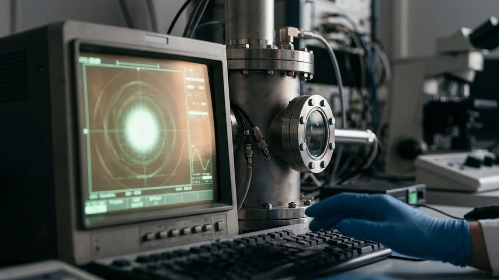
Column state moves on several timescales. Within a session, stage and lens temperatures stabilize over the first tens of minutes, so heavy work should follow a warm-up period rather than start cold. Over days, gun emission and filament geometry age, shifting current and alignment; over weeks, mechanical and vacuum changes accumulate. Each substrate type adds step-changes in working distance. The practical response is a tiered routine: a brief focus and stigmation check every session, a full spot-size and current verification at defined intervals or after any gun or vacuum event, and a qualification-pattern linewidth check per process lot.
Records make the cadence rational. Logging working distance, stigmator values, spot size, beam current, vacuum readings and filament hours lets the team see which parameter moves first and how fast, so the interval between full calibrations is chosen from evidence. When linewidth scatter later appears, the log distinguishes column drift from resist aging or dose error within minutes instead of days.
A workable routine fits in minutes and protects the whole session: vent and load, allow the stage and column to stabilize, confirm substrate height and working distance, run focus verification on the reference target, correct astigmatism and record the before-and-after images, verify beam current against the dose plan, and write a small qualification pattern before committing the real exposure. Each step has an acceptance threshold; any miss triggers the deeper full calibration instead of a live-process rescue.
Institutionalizing the routine matters as much as the optics. The same targets, the same scan settings and the same log format across operators make the column's condition comparable over time and across shifts. That is what converts electron beam lithography from a skill-dependent process into a qualified one.
CONCLUSION
Every nanometer of critical dimension in electron beam lithography passes through a spot that someone calibrated—or failed to. Focus sets the probe size, the stigmator sets its shape, and both drift on timescales that a process cannot see but a log can. A tiered routine with numeric acceptance criteria keeps the column inside its envelope and makes drift visible before it reaches the wafer.
Standardize the routine, record the evidence, and escalate to full calibration on defined triggers. Then the qualification pattern confirms a column in condition, dose and resist variables stay honest, and critical dimensions hold because the probe they depend on was never left to chance.
EVIDENCE CHECKLIST
FAQ
A brief focus and astigmatism check every session, after warm-up. A full verification—spot size, beam current and stigmation on the resolution standard—belongs at defined intervals or immediately after gun maintenance, vacuum events or large working-distance changes.
It is a set of quadrupole coils that counteracts residual astigmatism, making the beam spot round. Without it, the spot is elliptical and lines written in different orientations come out with different widths.
Elliptical spot shape from uncorrected astigmatism is a leading cause: the elongated spot widens features in one direction more than the other. Check stigmation across the relevant field positions before adjusting dose.
Yes. Working distance is measured to the substrate surface, so thickness, chuck stack and backside films all move the focal plane. Measure height per sample and verify focus at the actual write height.
They are a good starting point and save time, but their result should be verified with a captured image and a numeric sharpness or spot-size metric, especially for critical features and off-center field positions.
AUTHORITATIVE SOURCES
TECHNICAL REVIEW
Send the application, critical parameters and any drawing or process information available.
Discuss your application ↗