
Signal chain
Define readhead output, connector, cable, receiver, termination and controller sampling.
TECHNOLOGY / MOTION CONTROL
Prevent false position, jitter and dropouts by qualifying the encoder, cable, receiver, grounding and servo bandwidth as one signal chain.
Published
DIRECT ANSWER
Qualify encoder signal integrity by treating the readhead, cable, connector, receiver, grounding, motor drive and servo loop as one system. Define output format, cable length, frequency, termination, shielding, separation from power conductors, sampling, diagnostics and the worst-case motion profile. A clean signal at rest does not prove margin during acceleration or switching.
Ask the supplier for configuration-specific output limits and recommended cable practice, then test the installed route with motors, valves and drives operating. Measure noise, jitter, missed counts, CRC or alarm events, latency and loop stability. Separate electrical signal quality from mechanical accuracy so an EMC fix is not mistaken for a calibration fix.
ENGINEERING CONTEXT
A feedback loop can become unstable or intermittently wrong when a small encoder signal shares space with high-current switching. The buyer needs a wiring, receiver and servo evidence package, not a vague statement that the encoder is noise resistant.
Discuss your requirement ↗CRITICAL REQUIREMENTS
Define readhead output, connector, cable, receiver, termination and controller sampling.
Control route, shield, ground, separation, motor drive and switching-noise exposure.
Match update rate, latency, bandwidth, filtering and interpolation to the control loop.
Measure under motion, acceleration, power switching and cable installation conditions.
BUYER MATRIX
Give every shortlisted supplier the same process definition and request configuration-specific proof.
| Layer | Evidence | Failure |
|---|---|---|
| Output | Format, amplitude/frequency or frame limits | Receiver is overdriven or under-sampled |
| Cable | Length, impedance, shield and bend route | Noise, reflections or intermittent opens |
| Ground | Shield termination and ground strategy | Common-mode error or ground loops |
| Servo | Latency, filtering and bandwidth calculation | Jitter or oscillation |
| Validation | Noise and dropout logs under load | Static bench test hides production faults |
Start at the optical readhead and draw every electrical boundary to the controller: connector, cable, junction, receiver, interpolation, filter, sampling clock, servo calculation and diagnostic path. Mark motor power, brake, heater, valve and network cables that cross or run near the route. The drawing should identify which elements are supplied by SENFU and which are designed by the integrator.
Define the signal that the control loop actually uses. An incremental A/B/Z receiver, an analog sine/cosine interpolator and a BiSS-C serial input have different bandwidth and failure modes. The product choice is incomplete until the receiver and controller limits are known.
Output frequency rises with motion speed and scale pitch. Provide travel, peak speed, resolution setting and acceleration and ask for the configuration-specific signal frequency or serial update time. Then compare that result with the controller sampling rate, anti-aliasing, filtering and servo bandwidth. Leave margin for diagnostics and worst-case cable delay.
Avoid selecting a maximum speed without its resolution and interface conditions. A fine interpolation setting can consume more bandwidth than a coarse setting. Record the chosen configuration in the machine recipe so a later replacement does not silently change the signal demand.
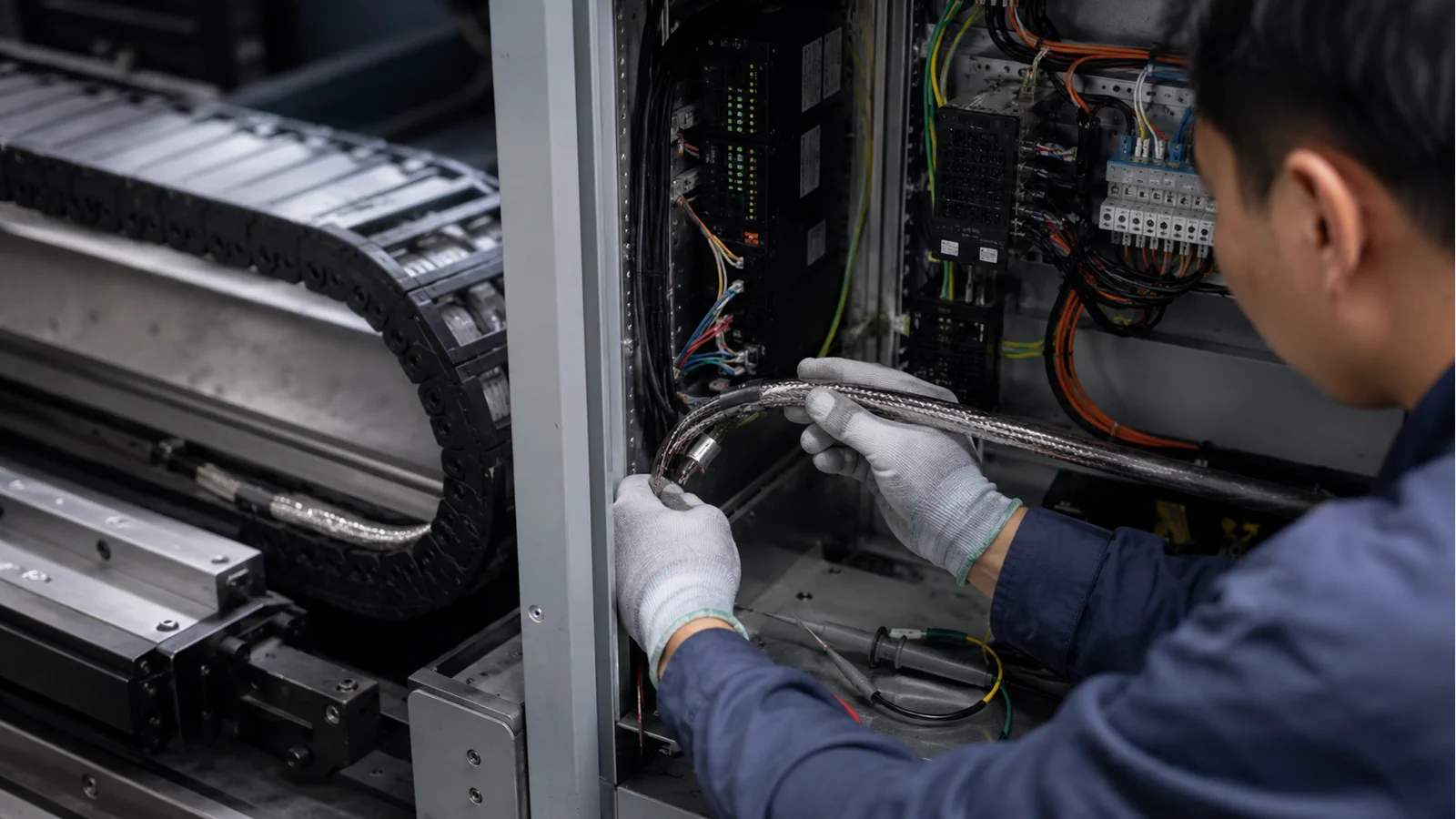
Keep encoder cables separate from motor and switching-power conductors and cross them at a controlled angle when separation is impossible. Define drag-chain bend, strain relief, connector orientation and service loop. A cable that transfers force to a small readhead can create mechanical error as well as electrical noise.
State shield termination at the readhead, connector, cabinet and receiver. Do not assume that more grounding is always better; a ground loop can add common-mode current. Ask the supplier for the recommended cable construction and receiver termination and document any deviation in the integration review.
Noise is an electrical variation, jitter is a time or edge variation and accuracy is a position error against a reference. They can interact in the servo, but the tests are different. Use an oscilloscope or receiver diagnostics for signal integrity, a reference instrument for position, and a control trace for loop response. Do not correct a scale or mounting issue by adding a filter.
For serial feedback, log frame errors, CRC, warning bits and latency. For incremental feedback, log count integrity, differential amplitude and index behavior during direction changes. The acceptance report should show the raw evidence and the processed result separately.
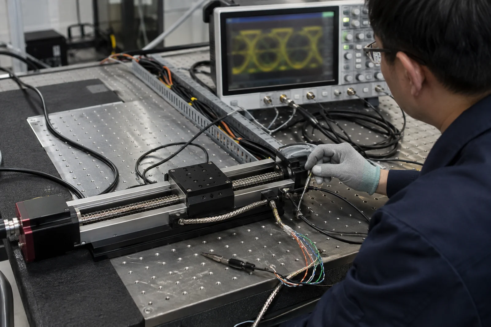
Static continuity and a slow jog are only pre-checks. Run the axis at the required acceleration while motor drives, brakes, heaters, valves and network devices operate. Repeat with covers installed and cables routed as they will be in production. Capture dropouts, alarms, edge distortion, control effort and reference position.
Change one variable at a time: cable route, shield bond, drive state, speed, acceleration or filter. This creates a causal record instead of a trial-and-error fix. Keep the controller and firmware revision with the data because a software update can change filtering or error handling.
A feedback filter can reduce noise while adding phase delay. Map encoder conversion, cable, receiver, digital filtering and controller computation into a latency budget. Check stability and tracking at the highest intended bandwidth and acceleration. If the axis is compliant or resonant, the correct remedy may be mechanical rather than more encoder filtering.
Absolute serial feedback adds frame timing that must be included in the loop. Incremental feedback can deliver edges quickly but depends on receiver integrity and count processing. The best interface is the one that meets the loop and fault requirements with measurable margin.
Give technicians a sequence: check connector and shield, inspect diagnostics, compare idle and motion traces, isolate the drive, substitute a known-good cable, verify receiver termination, then check mechanical alignment and reference. Record the symptom, conditions and corrective action. This prevents every feedback fault from becoming a product replacement.
Include a safe state for an invalid signal and a requalification step after a cable or grounding change. The goal is not only a robust design but a service process that protects the wafer, tool and schedule.
Provide output format, travel, speed, resolution, cable length, route, controller, motor drive, grounding, environment and acceptance instruments. Ask for output limits, recommended cable, timing, diagnostics and the supplier's test conditions. Mark the values that are guaranteed versus typical or configuration dependent.
SENFU can review the signal chain for SMG, SMG26 or SAG21 architectures and identify the installed EMC and servo tests that should close the decision. A complete answer links the product data to the actual cabinet and axis rather than promising generic noise immunity.
A signal path is easier to maintain when the acceptance record shows margin against the receiver and servo limits. Capture differential amplitude, edge quality, common-mode behavior, serial frame errors, latency and diagnostic thresholds at idle, acceleration, deceleration and the highest required speed. Note cable length, routing, shield bonds, termination and drive state for every trace. A pass with little margin may become an intermittent fault after a cable replacement or a cabinet change.
Store the raw oscilloscope or receiver files with the machine revision and link each observation to the mechanical and control test. If a filter, termination or grounding change is made, repeat both signal and position checks; an electrical improvement can add latency or hide a count error. This evidence lets procurement compare configured products and gives service engineers a repeatable decision tree instead of relying on a subjective noise screenshot.
Close the review with a named owner for every corrective action. The integrator should know whether the next step is a cable change, a receiver setting, a mechanical re-alignment, a firmware update or a new acceptance run. Put the limit and the measurement instrument in the action record so a supplier response can be checked without recreating the entire investigation.
CONCLUSION
Encoder signal integrity depends on the complete chain: output, cable, shield, receiver, drive environment and servo bandwidth. Test it under real switching and motion, then keep the raw evidence with the machine revision.
SENFU can map the interface and dynamic requirement to an encoder configuration and help define the EMC, latency and acceptance tests needed by the integrator.
SOLUTION ROUTES
EVIDENCE CHECKLIST
FAQ
The production route adds motor switching, cable length, grounding, vibration and controller timing. Static bench tests do not reproduce that signal chain.
Only after the source and servo latency are understood. Filtering can add phase delay and hide a mechanical or grounding fault.
Length, impedance, shielding, bend, connector, separation from power, termination and the supplier's recommended construction.
Use the installed cable and controller and log clock, frame, CRC, warning, latency and startup behavior during motor and switching activity.
Send encoder model, travel, speed, resolution, cable route, receiver, drive, grounding, environment, diagnostics and the observed fault or target.
AUTHORITATIVE SOURCES
TECHNICAL REVIEW
Send the application, critical parameters and any drawing or process information available.
Discuss your application ↗