
Readhead geometry
Control gap, lateral offset, pitch, yaw and roll through the full travel.
TECHNOLOGY / ENCODER INSTALLATION
Use the installation drawing to control readhead gap, parallelism, reference marks, cable forces and service repeatability on a precision axis.
Published
DIRECT ANSWER
Install a linear encoder from the model-specific drawing: control readhead gap, parallelism, lateral offset, pitch, reference-mark position, scale datum, cable force and service access over the complete travel. Check the gap at both ends and during motion, not only with the carriage parked. Use a stable mechanical datum and record the alignment method.
A readhead can report a fine increment while poor geometry creates interpolation error, dropouts or drift. Ask SENFU for the exact scale and readhead configuration, installation tolerances, reference-mark behavior and cable recommendation. Then validate the assembled axis with signal diagnostics and an independent position reference under the real speed, temperature and service conditions.
ENGINEERING CONTEXT
Linear encoder installation is where catalogue capability meets the machine. A micron-scale gap or a cable force that changes with travel can turn a good readhead into an intermittent or inaccurate feedback system.
Discuss your requirement ↗CRITICAL REQUIREMENTS
Control gap, lateral offset, pitch, yaw and roll through the full travel.
Define mounting surface, straightness, joints, reference mark and thermal path.
Route and strain-relieve the cable so motion and service do not load the readhead.
Measure signal quality, alignment and position before releasing the axis.
BUYER MATRIX
Give every shortlisted supplier the same process definition and request configuration-specific proof.
| Feature | What to record | Risk |
|---|---|---|
| Gap | Gauge or fixture method at both ends and during travel | Signal amplitude or interpolation changes |
| Parallelism | Scale-to-carrier and guideway relationship | Periodic error or dropouts |
| Reference | Mark location and homing direction | Wrong coordinate after service |
| Cable | Bend, force, connector and drag-chain path | Intermittent feedback |
| Service | Replacement datum and re-alignment procedure | Every change requires full redesign |
The installation drawing defines the mechanical conditions under which the optical signal is valid. Extract gap, lateral, pitch, yaw, roll, mounting-face and travel limits and place them on the stage assembly drawing. Identify fixed and moving datums, scale joints and the reference-mark direction. If the supplier offers multiple readhead or scale options, keep the selected configuration visible in the revision.
Do not use a generic CAD envelope as an installation tolerance. A small readhead may fit physically while the cable exit, cleaning tool or service hand cannot. Include assembly and maintenance access in the review so the alignment can be reproduced after a replacement.
The scale should be mounted to a surface whose geometry is stable over the travel and temperature range. Check flatness, straightness, joints, clamp spacing, adhesive or fastener method and the relation to the guideway. A scale that follows a bent carrier can transfer that geometry into the measured position even when the readhead gap is nominal.
Plan the reference mark and end-of-travel clearance. Keep the mark accessible to the commissioning routine and document the direction in which it is crossed. If the axis has hard stops or a collision-sensitive payload, include the mark in the safe homing and service procedure.
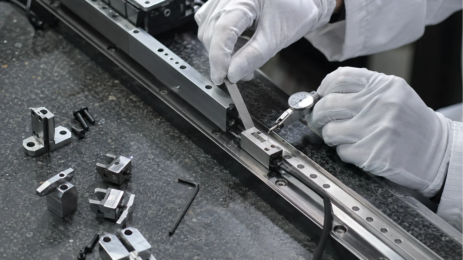
Use a gauge or supplier fixture to set the gap at the accessible points, then move the axis through the full travel and check for variation. Verify the readhead does not contact the scale during acceleration, cable flex or thermal expansion. Record the tool, method and environmental state used for the measurement.
A static gap check at the center can miss guideway pitch or a carrier that rises at the end. Measure both ends and, when practical, use a dial indicator or optical method to correlate gap with carriage position. The evidence is part of the installation record, not only an assembly note.
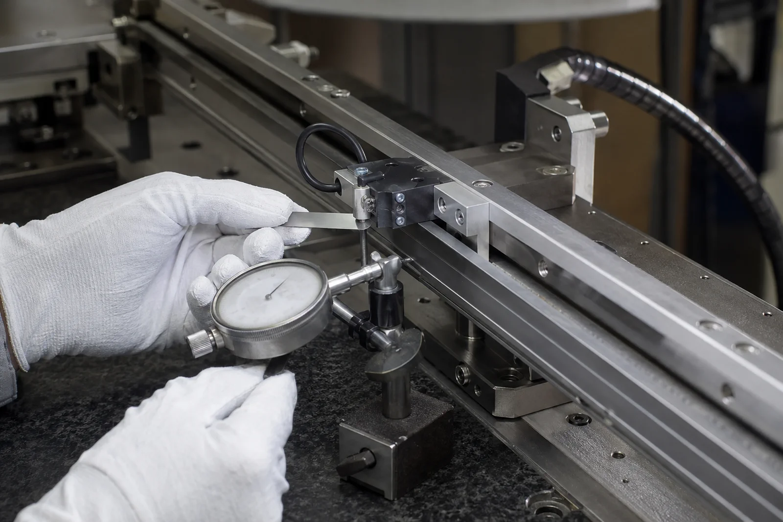
Optical readheads need the scale to remain within lateral and angular tolerance. Use two independent datums where possible: one for the scale and one for the readhead carrier. Adjust pitch and yaw before tightening fasteners, and record the order and torque or clamp method if it affects repeatability.
Do not compensate for a mechanical misalignment with controller scaling. A scale transform may remove a global error but cannot guarantee signal margin or protect against contact. If the stage flexes under payload, test alignment in the loaded state used by the process.
Route the cable so its bend and drag do not pull on the readhead or moving scale. Define minimum bend, loop orientation, strain relief, connector latch, drag-chain path and separation from motor power. Check the cable at both travel limits and during the fastest move.
A service loop should be long enough for removal but restrained enough not to brush the scale or carry particles into the process. Mark the cable and connector so a technician can reinstall the same orientation. The replacement procedure should include a gap and signal check before the machine is released.
First verify signal amplitude, diagnostics, reference mark and count or frame integrity. Then compare encoder position with an independent reference over the travel and at the process speed. This separates a wiring or optical problem from scale, mounting or stage accuracy. Record the controller, interpolation, filter and cable used.
Run the check after warm-up and after a controlled service reinstallation. If the signal is stable but position shifts, investigate thermal and mechanical terms; if position is repeatable but signal margin is low, revisit gap, contamination, cable and receiver conditions.
Write a service instruction with datum surfaces, fixtures, fastener sequence, gauge, reference-mark routine, cable route and pass/fail limits. Record the original alignment values and a photo or drawing of the installed configuration. A small replacement readhead or scale change can alter the coordinate, so do not rely on memory.
Include contamination control and packaging. The scale and optics should be protected during cleaning and handling, and the technician should know which solvents or tools are permitted. Requalification should be proportional to the change but always include gap, signal and reference position.
Provide travel, stage drawing, guideway, gap, scale datum, reference mark, cable route, speed, temperature, environment, controller and service plan. Ask the supplier for the exact drawing, tolerances, fixture recommendation, signal limits and acceptance method. Mark any installation assumption that is not documented.
SENFU can review SMG20, SMG26 or another optical encoder against the complete mechanical envelope. The output should be a controlled installation and a repeatable verification record, not a readhead that merely fits inside the cover.
Installation acceptance should end with a datum record that another technician can reproduce. Photograph or draw the scale and readhead reference surfaces, record gap readings at defined travel points, note cable orientation and keep the fixture or gauge identifier. Store signal diagnostics, reference-mark repeatability and an independent position check with the same stage revision. This turns a careful assembly into evidence that survives a later move or replacement.
Write the release sequence in the order it will be used: clean and inspect, mount the scale, set the readhead, route and strain-relieve the cable, verify signal, run the reference mark, measure the travel and approve the axis. Define what requires a full requalification—such as a scale change, readhead replacement, carrier adjustment or cable route change—and what can be checked at maintenance. A supplier review is strongest when the drawing, fixture and acceptance limits are connected.
Include the environmental state in the datum record. Note temperature, warm-up, vacuum or purge condition, cleaning status and payload where they affect the geometry. When an axis is released to production, the operator should be able to see which checks are quick daily verifications and which require an engineering re-alignment. This avoids turning a small maintenance event into an undocumented change to the machine coordinate.
CONCLUSION
Linear encoder performance depends on the gap, datum, angular alignment, cable force and service procedure across the entire travel. Use the supplier drawing as a control document, then verify signal and position on the assembled stage.
SENFU can map the mechanical envelope to a documented encoder configuration and define the fixtures and evidence needed before the axis is released.
SOLUTION ROUTES
EVIDENCE CHECKLIST
FAQ
No. Check both ends and, when practical, during motion because guideway pitch, carrier flex and thermal movement can change the gap.
It may address a measured global term, but it cannot guarantee optical signal margin or prevent contact. Fix the mechanical geometry first.
Show scale datum, readhead gap, lateral and angular limits, reference mark, travel, cable exit, service access and selected configuration.
Repeat gap, signal, reference-mark and independent position checks with the documented service fixture and pass/fail limits.
Send travel, stage drawing, guideway, gap, cable route, speed, temperature, controller and environment.
AUTHORITATIVE SOURCES
TECHNICAL REVIEW
Send the application, critical parameters and any drawing or process information available.
Discuss your application ↗