
Feedback quality and mapping
Encoder or interferometer resolution and noise, scale error profile and its mapping, readhead configuration (multiple heads, averaging) and mounting stability over the full travel.
TECHNOLOGY / LITHOGRAPHY STAGE METROLOGY
What stitching accuracy really depends on in maskless lithography: stage position metrology, encoder scale mapping, air-bearing stage behavior, environmental drift and the acceptance tests that qualify field stitching.
Published
DIRECT ANSWER
In maskless and e-beam lithography, large fields are written as tiles that must join within a specified overlay tolerance; the error at the tile boundary is stitching error. Because the exposure tool projects or writes each tile at a position defined by the stage, stitching accuracy is governed first by stage metrology: the quality of the encoder or interferometer feedback, the mapping of that feedback against a reference, straightness and angular error motions of the stage, and the stability of the metrology frame against temperature.
An encoder-based stage can reach sub-micrometer stitching accuracy when the scale errors are mapped and compensated, the readhead geometry is stable, and the environment is controlled; the acceptance test should measure stitching directly, by exposing tile-pair patterns and measuring boundary alignment on a metrology tool, rather than inferring it from axis accuracy numbers alone.
ENGINEERING CONTEXT
Procurement documents often specify stage accuracy as a single axis number, then discover stitching errors three to five times larger at field boundaries. The gap comes from what the single number does not contain: differences between adjacent tile positions on the scale, cross-axis error motion coupling into in-plane position, scale error periodicity that aliases with the tile pitch, thermal drift of the metrology frame between tiles, and write-timing interaction with stage dynamics. None of these appear in a static positioning-error specification, yet each lands directly at the stitch boundary where the user's overlay requirement lives.
Discuss your requirement ↗CRITICAL REQUIREMENTS
Encoder or interferometer resolution and noise, scale error profile and its mapping, readhead configuration (multiple heads, averaging) and mounting stability over the full travel.
Straightness, flatness, pitch, yaw and roll error motions over travel, Abbe offsets between measurement axis and exposure plane, and the dynamic behavior at writing velocity.
Temperature stability of scale, frame and substrate, gradients between tiles written minutes apart, and vibration isolation adequate for the writing process.
A defined acceptance test exposing tile boundaries in both axes with matched process conditions, measured on a calibrated metrology tool, with the error budget and acceptance limits agreed before purchase.
BUYER MATRIX
Give every shortlisted supplier the same process definition and request configuration-specific proof.
| Error contributor | Mechanism at the stitch boundary | Characterization method | Typical mitigation |
|---|---|---|---|
| Scale (grating) error | Adjacent tiles are written at different scale positions; uncorrected scale errors appear directly as stitch offset | Scale mapping against a laser interferometer or straightedge over full travel | Linear and periodic error compensation tables in the controller; multi-head averaging |
| Straightness and angular error motion | Cross-axis motion and yaw change the in-plane position between tiles, especially with Abbe offset | Capacitive or optical probes on a reference artifact over travel | Minimize Abbe distance; dual readheads across the axis; mechanical alignment of guides |
| Thermal drift of metrology frame | Tiles written minutes apart land on a frame that has grown or bent between exposures | Long-duration position drift log at fixed substrate with temperature recorded | Low-CTE frame materials, symmetric structures, enclosure temperature control, delay management |
| Encoder noise and interpolation error | Position noise at writing instant translates into line placement jitter within and between tiles | Jitter measurement per supplier guidance; subdivision error testing | High-quality optical interpolation, signal quality discipline, filtered velocity loops |
| Write-timing and stage dynamics | Pixel placement referenced to a stage position that lags or leads the actual optical position | Correlate stage data with written test patterns at production velocity | Synchronized write trigger from encoder position, adequate settling before tile start |
A maskless tool builds a large area by writing fields, and the exposure system handles the geometry within a field. The stage handles the geometry between fields. When tile N+1 is written, its placement is whatever the stage position feedback said, translated through the machine's geometry into substrate coordinates. Every error in that translation appears at the boundary between tiles as an offset, rotation or distortion the user sees as stitching error. This is why two tools with identical optics and identical nominal stage accuracy can show very different stitch quality.
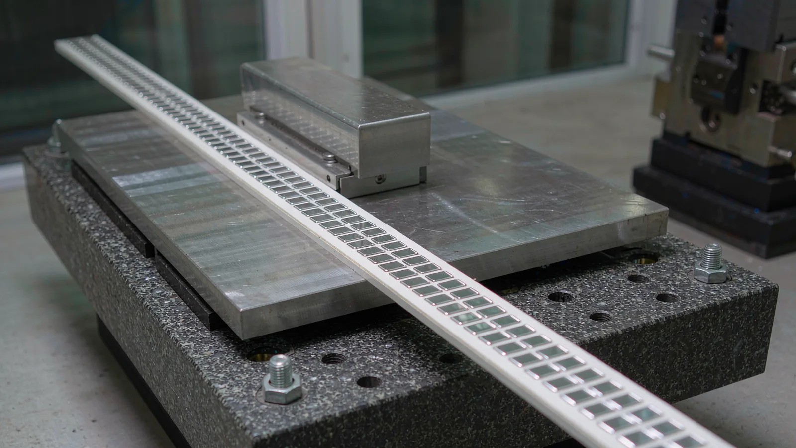
The measurement chain is the foundation. An optical encoder with sub-micrometer resolution provides position feedback whose systematic error is dominated by the scale's graduations and by readhead geometry. Unlike an interferometer, an encoder measures directly at the stage with no beam path through air, which makes it robust to environmental index changes and compact enough for OEM integration; the cost is that scale errors become stitch errors unless they are mapped out. That trade is exactly why encoder-based lithography stages succeed or fail on calibration discipline.
The budget should be built from the stitch requirement backward: if the process tolerates 150 nm stitch overlay, the budget allocates shares to scale mapping residual, error motion, thermal drift, noise and write-timing, each with a characterization method. A tool specified this way can be accepted by measurement instead of by hope.
Scale error mapping is the first lever. A stage supplier maps the encoder's position error against a reference over full travel and loads a compensation table; the residual after compensation, not the raw scale datasheet, is what belongs in the error budget. Residuals typically contain a small linear component plus low-order periodic terms; multi-head configurations that average two or more readheads spaced to suppress harmonic scale errors reduce the periodic part before compensation even starts. This is standard practice in high-accuracy stages and is worth verifying explicitly in procurement.
Readhead mechanical stability matters as much as the scale. A readhead bracket that relaxes after thermal cycling shifts the measurement datum by a fraction of a micrometer, which repeats at every stitch boundary. Mounting design, materials with matched thermal expansion, and a verification check of datum stability over temperature belong in the design review. On rotary axes, angular encoder stages follow the same logic with the additional subtlety that eccentricity between scale and rotation axis maps directly into angle error and is best suppressed by multi-head averaging around the circumference.
Air-bearing stages are the natural partner for this metrology: they remove guide friction and its stick-slip signature from the position loop, keep yaw and roll error motion at the arcsecond level over travel, and let the encoder close the loop on a stage that moves smoothly at writing velocity. The combination of air-bearing guides, mapped optical scales and encoder-synchronized write triggering is the practical recipe for sub-micrometer field stitching on compact maskless tools.
These clauses convert stitching intent into checkable requirements:
Between writing one tile and the next, minutes pass. If the machine frame, scale or substrate changes temperature in that interval, the second tile lands on coordinates that no longer match the first. The encoder cannot prevent this, because the scale itself is the reference: if the scale's support grows, positions measured against it move with it. The defense is material and structural: low-expansion frame materials, symmetric structures that bend rather than grow asymmetrically, and enclosure-level temperature stability so that gradients, not just absolute temperature, are controlled.
Substrate effects add a second layer. The substrate clamped to the stage has its own thermal expansion, and the stitch relationship is defined in substrate coordinates, not stage coordinates. Tools that write large fields on glass or semiconductor substrates control the substrate's temperature or compensate for its expansion in the layout; otherwise a temperature difference between tiles converts directly into stitch error at a rate set by the substrate's expansion coefficient.
A practical drift characterization is inexpensive and revealing: park the stage holding a written reference pattern, log reported position and temperature for hours, and correlate the two. The result tells the integrator whether the remaining stitch error will be dominated by drift or by the compensation residuals, which determines where the next engineering hour is best spent. SENFU supplies encoder configurations for lithography stages with the geometry and stability documentation needed to run this analysis, and supports the integration review from stage design through stitching acceptance.
The acceptance test that matters exposes what the user's process will see: adjacent tiles written under production conditions, with the boundary pattern designed for metrology, such as vernier or cross-coupled gratings spanning the seam in both axes. Measure the boundary alignment on a calibrated metrology tool, across multiple seam locations and multiple field pairs, including seams written early and late in a long job to expose drift. Report the distribution, not just a best case.
Correlate the measured stitch errors with stage data recorded during writing: encoder position at tile start and end, temperature logs, and error-motion traces. This correlation turns a failing number into a root cause: scale residual shows as a repeatable function of stage position, drift shows as a trend with time, dynamics show as velocity-dependent placement shifts. Each has a different fix, and only direct measurement distinguishes them.
Agree the error budget and limits before purchase, in the specification, so acceptance is a measurement against pre-agreed numbers rather than a negotiation. SENFU supports this with application engineering review of the stage's encoder configuration, mapping and compensation documentation, and the stitching test plan, so that encoder-based metrology delivers its full accuracy where the user's requirement actually lives: at the field boundary.
CONCLUSION
Field stitching in maskless lithography is governed by stage metrology: mapped optical encoder scales, stable readhead geometry, minimized Abbe offsets, air-bearing stage dynamics and a thermally stable metrology frame. A single axis-accuracy number does not predict stitch quality; the error budget and its characterization methods do. Tools that qualify stitching by direct boundary measurement, correlated with stage and environmental data, turn stitching from a field surprise into a pre-agreed acceptance measurement.
For a SENFU technical review, send the stage design, encoder configuration, error budget draft and stitching test plan. SENFU can check the metrology chain against the stitch target and provide the configuration documentation needed for a defensible acceptance test.
SOLUTION ROUTES
EVIDENCE CHECKLIST
FAQ
Positioning accuracy is usually a single-axis, whole-travel statistic. Stitching error is a differential measurement between two positions, so it is sensitive to scale error differences at those positions, cross-axis error motion with Abbe offset, thermal drift between tiles and write-timing effects. These are bounded only when the error budget treats them explicitly.
Encoder-based stages achieve sub-micrometer stitching when scales are mapped against a reference and compensated, readheads are multiplied and averaged to suppress harmonic errors, and the metrology frame is thermally stable. Encoders measure directly at the stage and avoid interferometer beam-path sensitivity to air index, which is an advantage in compact tools; interferometers remain the reference for the mapping step.
Mapping measures the encoder's position error against a reference interferometer or straightedge over full travel and loads a compensation table into the controller. It is performed at build and repeated after major service or if datum stability checks suggest change. The mapped residual, not the raw scale datasheet error, belongs in the stitch budget.
The encoder measures position relative to the scale. If the scale, its support or the frame grows between writing one tile and the next, the second tile's coordinates shift with them. Control comes from low-expansion materials, symmetric structure and enclosure temperature stability, plus substrate temperature management for large fields.
Directly measured boundary alignment between adjacent tiles written under production conditions, using metrology-friendly seam patterns, sampled across multiple seams, field pairs and job durations, measured on a calibrated tool. Report the distribution and correlate outliers with stage, temperature and timing data for root cause.
Send the stitch accuracy target and error budget draft, stage concept and travel, encoder configuration including readhead count and placement, thermal design of the metrology frame, and the intended acceptance test. SENFU application engineering can review the metrology chain and provide configuration-specific documentation for the qualification file.
AUTHORITATIVE SOURCES
TECHNICAL REVIEW
Send the application, critical parameters and any drawing or process information available.
Discuss your application ↗