
Definitions in the specification
State subdivision error and jitter as separate line items with their own test methods, bandwidths and statistics.
TECHNOLOGY / ENCODER METROLOGY
Separate subdivision error, noise-driven position jitter and mechanical vibration in encoder data sheets, and specify the test conditions that make vendor numbers comparable.
Published
DIRECT ANSWER
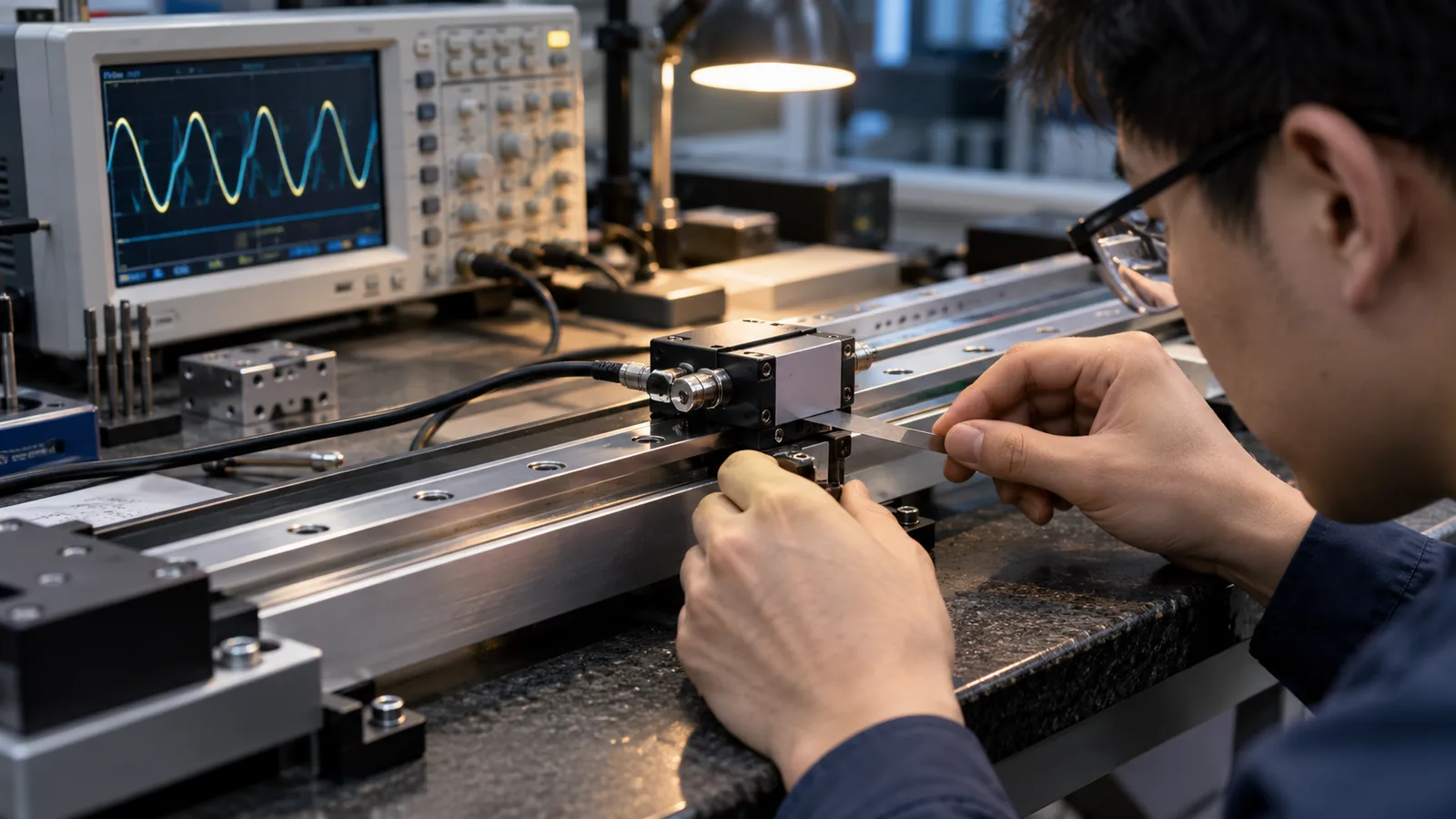
Subdivision error is the periodic deviation that appears when the electronics divide one signal period into finer steps: its amplitude scales with signal quality and repeats every signal period, so it appears once per cycle of the scale pitch. Position jitter is broadband: it comes from electrical noise, quantization and the environment, and it does not repeat with the scale period. The two are specified with different methods and reduced with different countermeasures.
To compare vendors, require the test conditions with every number: signal amplitude and balance, gap, bandwidth of the measurement, averaging applied and the statistic reported (peak-to-peak, RMS or sigma). For servo stability, the relevant quantity is jitter within the servo bandwidth; for metrology applications, subdivision error within the working speed range matters. A number without its measurement conditions cannot be compared to another vendor's number.
ENGINEERING CONTEXT
Buyers comparing encoder data sheets routinely stack an interpolation error figure from one vendor against a jitter figure from another, measured with different bandwidths, different averaging and different statistics. The resulting shortlist is a comparison of marketing conditions, not of hardware. The discipline that fixes this is to define the measurement for each term, ask for the raw conditions, and validate the combined effect on the actual machine.
Discuss your requirement ↗CRITICAL REQUIREMENTS
State subdivision error and jitter as separate line items with their own test methods, bandwidths and statistics.
Require signal quality, gap, speed, bandwidth, averaging and statistic for each published figure.
Validate the combined position noise on the real stage against a reference sensor, within the servo bandwidth the machine will actually run.
BUYER MATRIX
Give every shortlisted supplier the same process definition and request configuration-specific proof.
| Aspect | Subdivision (interpolation) error | Position jitter |
|---|---|---|
| Physical origin | Periodic deviation from dividing the analog signal cycle into steps; sensitive to signal amplitude, balance, harmonics and gap | Broadband noise from electronics, quantization, cabling and environment, plus real mechanical vibration |
| Signature in data | Repeats once per signal period; visible as a ripple locked to scale pitch versus position | No fixed relation to scale period; visible as broadband scatter in a static or moving position record |
| Typical specification | Peak-to-peak or RMS fraction of one signal period under defined signal quality | RMS or sigma over a defined bandwidth, sometimes as noise density |
| Key test conditions | Amplitude, DC balance, harmonic content, gap, speed across the working range | Measurement bandwidth, averaging, sensor referenced, mechanical isolation of the test |
| Main countermeasures | Better signal quality, calibrated interpolation, gap control, matching electronics to the readhead | Lower-noise electronics and grounding, bandwidth shaping in servo, mechanical isolation, filtering with its latency cost |
| Where it hurts | Cyclic error in metrology and stage maps; velocity ripple at constant speed | Servo stability margin, line-edge roughness, acoustic noise, surface finish in scanning modes |
Incremental encoders produce analog cycles as the scale moves. Interpolation electronics divide each cycle into countable steps. Whatever imperfection the analog signal carries, amplitude imbalance, DC offset, harmonics, contamination of the optical field, reappears as a periodic deviation in the interpolated position. Because that deviation repeats every signal period, it is called subdivision or interpolation error, and its amplitude is a property of signal quality as much as of the electronics.
Position jitter is different in kind. It is broadband scatter around the mean position, produced by electronic noise, quantization, grounding and cabling, and on a real stage by genuine mechanical vibration. It does not care where the scale is in its cycle. Confusing the two families leads to wrong purchases: a lower-noise electronics box will not remove a signal-quality-driven interpolation error, and a better optical field will not fix a grounding scheme that radiates into the cable.
Every published error figure is a pair: a value and the conditions that produced it. When a data sheet states an interpolation error of, for example, a fraction of a signal period, ask which amplitude and balance the signal had, at which gap, at which speed, measured over how many periods, reported as peak-to-peak or RMS. When a jitter figure appears, ask the measurement bandwidth, the averaging, whether the stage was moving or static, and which reference sensor anchored the measurement.
Two vendors can quote the same number for different hardware, or different numbers for the same hardware, purely through conditions. The correct buyer behavior is to issue a measurement-conditions sheet with the RFQ, so all respondents fill in the same template. This is the same discipline required for supplier qualification in general, as described in the optical encoder supplier qualification guide, and it connects to the signal-integrity and EMC treatment in the dedicated article on encoder signal integrity.
Interpolation error is not a constant. Signal amplitude and balance change with speed and with the analog bandwidth of the readhead, so the subdivision error at scanning speed can differ from the value measured quasi-statically. For metrology and stage-mapping applications, require the subdivision error stated across the working speed range, not only at a single reference condition.
The verification method is straightforward and should appear in the acceptance plan: while the stage moves at constant velocity, record the encoder position against a reference interferometer or an independent high-accuracy sensor, and analyze the position error spectrum. The component locked to the scale period is subdivision error; the broadband floor is jitter and reference noise. This single record separates the two families in the buyer's own system, with no dependence on vendor test rigs.
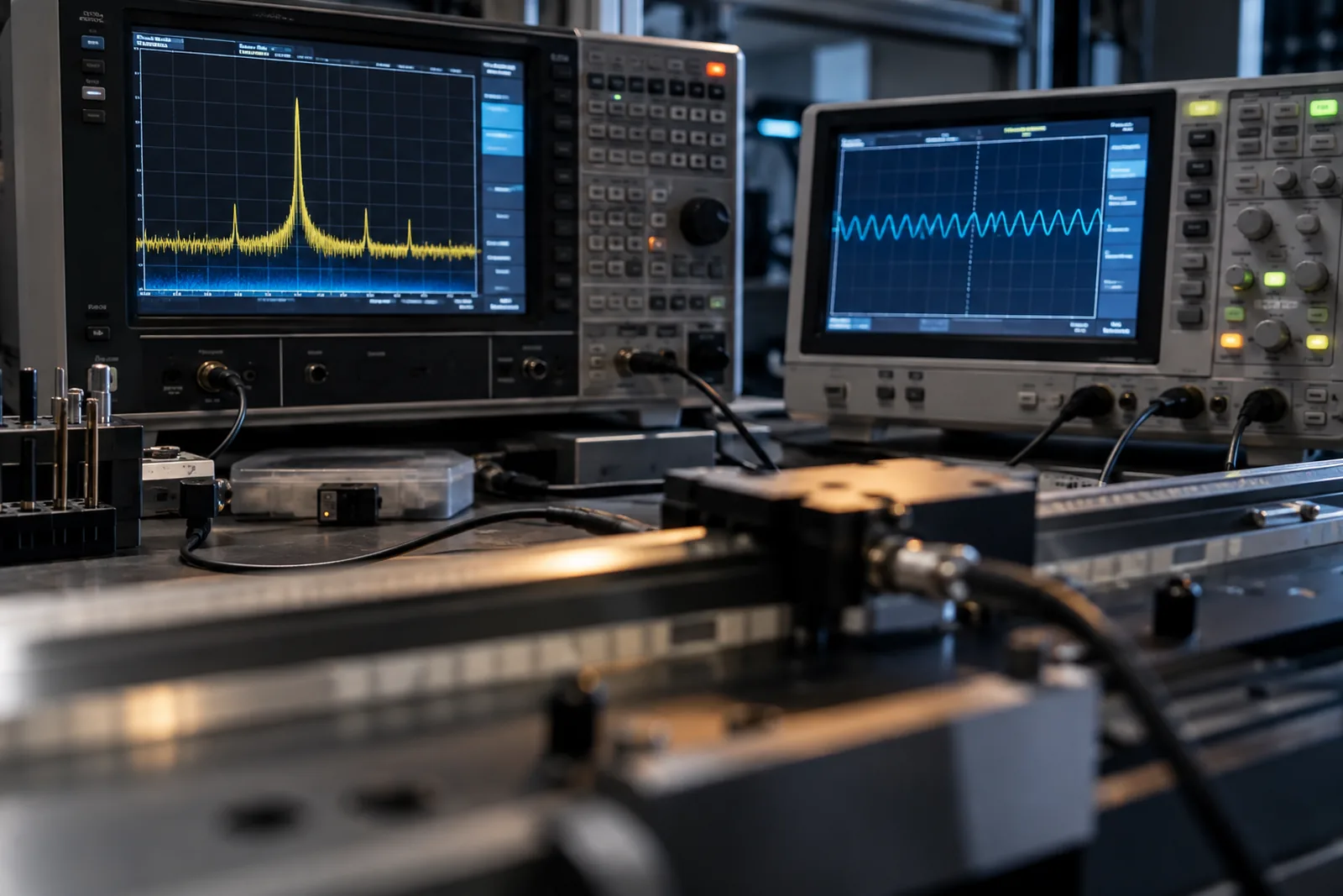
In a servo loop, the jitter that matters is the jitter inside the loop bandwidth. Outside it, the mechanics and the controller respond differently, and high-frequency content may matter only for surface finish or acoustic reasons. When comparing systems, therefore, compare jitter within the bandwidth the application will run, and be explicit about the filtering that each figure includes.
Filtering is a trade, not a free lunch. Additional filtering in the position path reduces reported noise but adds phase lag, which consumes servo stability margin and can create the very oscillation it was meant to hide. The honest sequence is: reduce noise at the source with clean signal, proper grounding and appropriate cable practice; shape the bandwidth in the servo deliberately; and validate the combined dynamic behavior with the actual load, as discussed in the interpolation error testing article.
A procurement-ready encoder specification separates the two families and their conditions: subdivision error as peak-to-peak and RMS fraction of a signal period, at defined amplitude, balance, gap and speeds across the working range; position jitter as RMS within the application servo bandwidth, with the measurement bandwidth and reference sensor stated; signal quality requirements for amplitude and DC balance at the connector; and an acceptance test on the delivered stage that reproduces the constant-velocity error spectrum against a traceable reference.
SENFU optical encoder documentation follows this division between catalogue figures and installed evidence, and the applications team can provide the measurement-conditions template so all candidates respond on comparable terms.
CONCLUSION
Subdivision error and position jitter describe different physics, are measured with different methods, and are fixed with different countermeasures. A buyer who accepts numbers without their measurement conditions is comparing vendor test rigs, not encoders. Define the conditions in the RFQ, validate the combined effect with a constant-velocity error spectrum against a reference on the real stage, and judge jitter inside the servo bandwidth the machine will actually run. That process converts data-sheet numbers into a position feedback specification the machine can honor.
EVIDENCE CHECKLIST
FAQ
They describe the same family: the periodic deviation created when electronics divide one analog signal cycle into steps. Interpolation error is the common name for the electronics side; subdivision error emphasizes that the deviation repeats every signal period and scales with signal quality.
With a defined measurement bandwidth, a stated averaging and a reference sensor anchoring the measurement, reported as RMS or sigma. Jitter must be quoted inside a bandwidth, because a number without bandwidth cannot be compared between vendors or reproduced on the buyer's machine.
No. If the analog signal arrives with imbalance, harmonics or insufficient amplitude, calibrated electronics reduce but cannot remove the periodic error. Signal quality at the readhead, correct gap and clean cabling come first; electronics come second.
Because the data sheet figures were measured under vendor conditions. On a real machine, mechanical vibration, grounding, cable routing and servo tuning add broadband content that the catalogue never included. Validate with a constant-velocity error spectrum on the actual stage to see which family the noise belongs to.
AUTHORITATIVE SOURCES
TECHNICAL REVIEW
Send the application, critical parameters and any drawing or process information available.
Discuss your application ↗