
Defined measurand
State whether the result is readhead position, carriage position or the process point against an external datum.
TECHNOLOGY / PRECISION METROLOGY
Plan encoder interpolation error testing with long-travel mapping, sub-period sampling, independent metrology, uncertainty and configuration-level acceptance evidence.
Published
DIRECT ANSWER
Encoder interpolation error testing is the short-range part of a position-acceptance test. It checks whether the encoder reports a faithful position while the readhead moves through one signal period, rather than only checking average scale error over a long travel. Test it alongside baseline scale error, position noise, repeatability and complete-axis positioning error.
Define the motion envelope, freeze the encoder and signal-chain configuration, compare encoder position with an independent displacement reference, and sample both long travel and sub-signal-period motion. Repeat in both directions at relevant speeds and thermal states, analyze residuals in position and phase or frequency domains, and set a pass/fail rule that includes measurement uncertainty. The result must remain tied to the purchased configuration.
ENGINEERING CONTEXT
A fine digital increment can coexist with periodic position error or a larger complete-axis error. A defensible acceptance plan must show which term was measured, what the result includes and whether the configured encoder, receiver and installed axis reproduce the result under the buyer's motion and environment.
Discuss your requirement ↗CRITICAL REQUIREMENTS
State whether the result is readhead position, carriage position or the process point against an external datum.
Record scale, readhead, output, receiver, cable, filtering, firmware, mounting and compensation.
Combine a long-travel map with fine sampling across multiple phases inside the signal period.
Predefine uncertainty, statistics, pass/fail limits, raw-data retention and requalification triggers.
BUYER MATRIX
Give every shortlisted supplier the same process definition and request configuration-specific proof.
| Term | What it describes | What it does not prove |
|---|---|---|
| Baseline scale error | Position-dependent deviation over a longer interval or measuring range | Fine periodic error inside one signal period |
| Interpolation error | Deviation while converting the periodic sensing signal into position between cycles | Every mechanical or thermal error in the axis |
| Position noise | Random variation over a defined bandwidth and observation period | Absolute accuracy or scale calibration |
| Repeatability | Variation on returning under specified direction, speed, load, servo and environment | Encoder noise alone |
| Complete-axis error | The assembled stage or machine against an external reference | Encoder-only performance without isolation evidence |
An optical encoder converts a periodic scale signal into position. Electronics estimate position between cycles by interpolating phase. If the channels are not ideal sinusoids, or sensing, filtering, alignment or signal processing distorts their relationship, the estimate can move above and below true position within one signal period. The error can repeat at the same spatial phase, so a long-step check can miss it.
HEIDENHAIN's accuracy-data note describes interpolation accuracy separately from measuring-standard accuracy and position noise, and identifies signal period, graduation, scanning structures, sensors and signal processing as influences. That is industry guidance, not a SENFU performance statement. Its companion note on surface effects explains that periodic deviations can appear as recurring form effects in machine-tool workpieces. For an OEM, the question is whether the residual is large, repeatable or dynamically coupled enough to affect the application.
Interpolation testing matters when an axis performs short moves, dwells at a target, follows a slow contour or feeds a sensitive velocity loop. It also matters when a specification quotes fine resolution but gives no interpolation or noise evidence. Test the configured encoder at the production controller interface; an isolated readhead result does not represent the installed axis.
Start with the motion the machine will actually execute. Record travel and the critical working window, smallest move, normal and maximum speed, acceleration, settle or dwell behavior, direction changes, load, payload position, servo state and the point whose position matters. State whether evaluation occurs during motion, under servo or after mechanical settling.
Add environment and output conditions: temperature and gradients, warm-up state, air or vacuum operation, contamination, vibration, supply, receiver or controller input, cable and connector, interpolation or resolution setting, filters, sample clock and compensation. A fine-move test with a laboratory receiver is not production acceptance through a different cable and input stage.
Define the measurand before choosing a limit. Is it encoder position at the readhead, carriage position at a tool point, or process-point position relative to a fixed datum? Identify any Abbe offset and whether the result is raw, compensated, filtered or transformed. If a criterion is unknown, mark it as an engineering decision; do not borrow a supplier's typical value or turn resolution into accuracy.
Interpolation is a property of a configured sensing and processing path, not just a model family. Before testing, record the exact readhead, scale type and length, pitch or signal period, reference marks, interpolation or resolution setting, output format, supply, cable, connector, receiver, termination, filter, firmware, controller and compensation revision.
Include the documented mechanical installation state: scale datum, readhead gap, alignment, fastener or adhesive method, cable routing, load and service fixture. Record drawing and data-sheet revisions and the tested item's serial or batch. If a field is unknown, leave it open and make closure part of acceptance.
The same discipline applies to public SENFU data. Product pages identify configuration-specific resolution, scale pitch, output and materials, but do not authorize an interpolation value for every option. Use the optical encoder range as a starting point, then request the exact orderable configuration and test conditions. A receiver, interpolation, cable, filter or mounting change can require a new test even when the model name is unchanged.
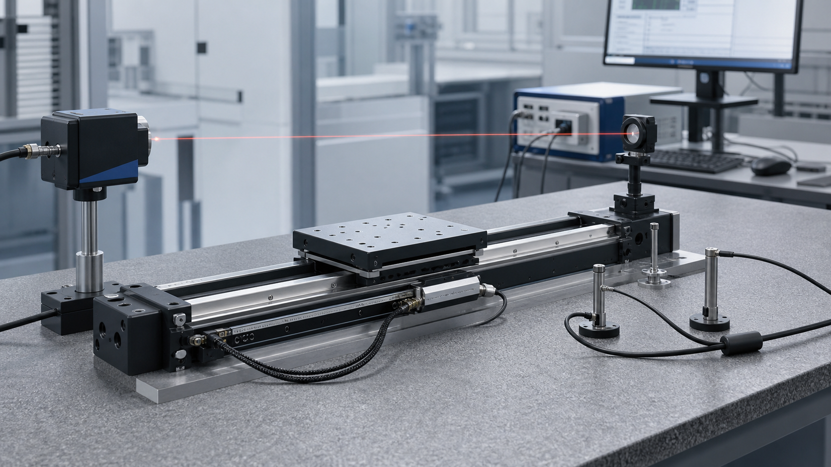
Use an independent displacement reference appropriate to the required uncertainty. A laser interferometer is one option for a linear axis; another calibrated displacement instrument may suit a shorter or enclosed travel. The reference measures axis or target motion while the encoder reports its own position. Align the reference line with the point of interest and document Abbe offset, target geometry, dead path and fixture stiffness.
A NIST ultra-precision stage metrology paper shows why the reference setup belongs in the evidence: its interferometer measurements account for air refractive index and stage or scale growth, and its uncertainty analysis includes environment and alignment. NIST's length-and-traceability program likewise identifies air refractive index and artifact thermal expansion as major high-accuracy contributors. An interferometer result is therefore not automatically encoder-only performance.
Synchronize encoder data, reference displacement, trigger or sample clock, servo state, drive signals and environmental channels. Use a common time base or document latency and alignment. Capture raw analog channels when available, plus decoded controller position. Log temperature near scale and structure, air pressure and humidity when relevant, supply and receiver diagnostics, and the motion recipe. Record instrument identity, calibration, range, bandwidth, sampling, filtering and uncertainty.
Before acceptance data, verify reference scale factor, beam alignment, target return, cable timing, sensor saturation, receiver margin, vibration and fixture loading. Run a no-motion dwell for the noise floor and a known larger move to confirm sign, scale and coordinate registration.
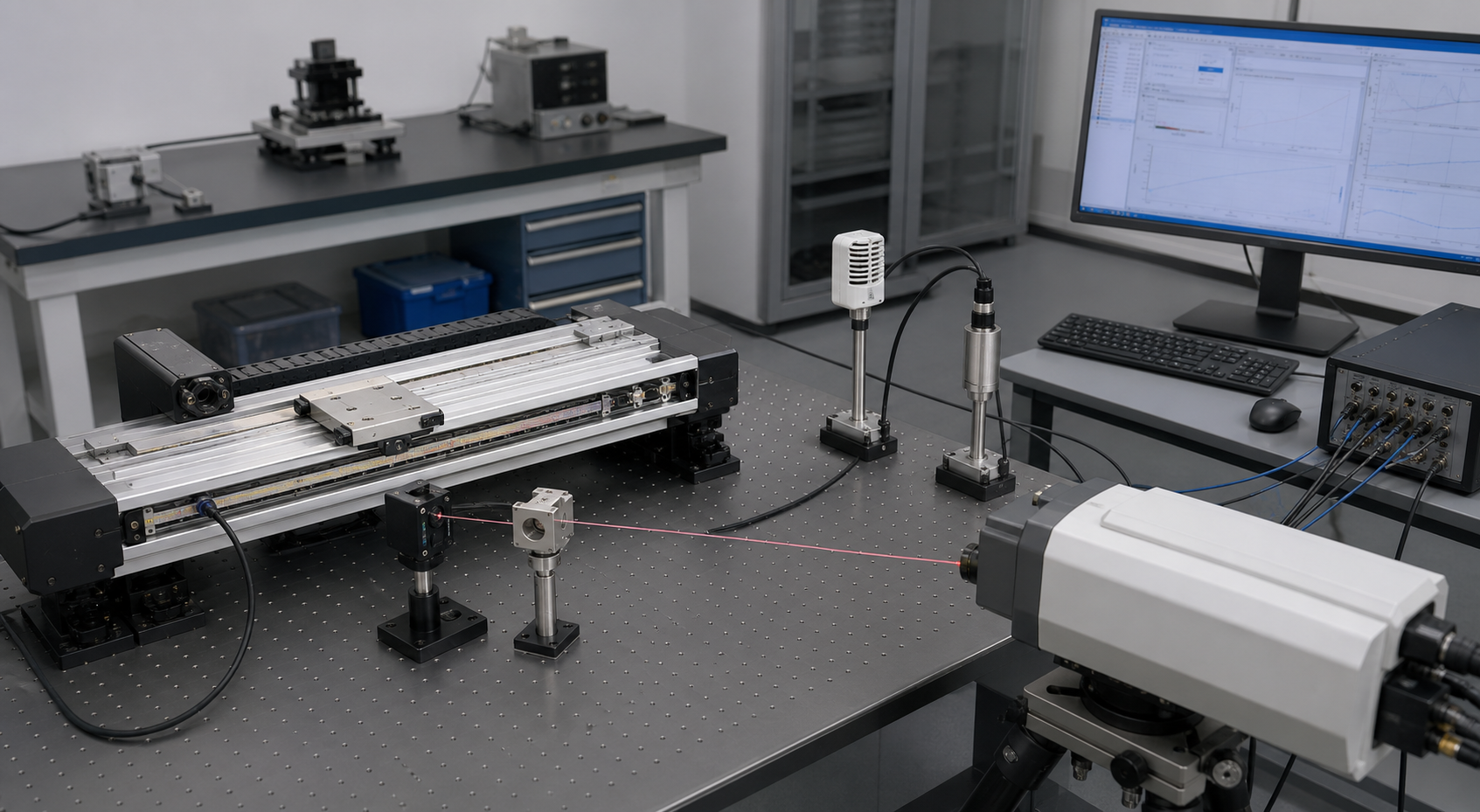
Map the working travel or complete acceptance range with target locations that expose global slope, local scale structure and end effects. Use the same reference datum for forward and reverse motion. At each target, record commanded, encoder and independent reference positions, direction, speed, settle condition, servo state and environment. Keep enough dwell to distinguish a settled value from a moving average without hiding an application transient with an undocumented filter.
Repeat in both directions and at relevant speeds. A straight residual trend can indicate scale calibration or thermal growth; direction-dependent separation can indicate mechanics, servo behavior or hysteresis. A local feature fixed to the scale may relate to graduation or installation, while one changing with electronics or filtering points elsewhere. The long map provides context for the short-period result; it does not replace it.
Determine the signal period from the frozen configuration, then sample positions across it with increments and starting phases fine enough to expose the residual. Do not sample only at cycle boundaries, which can hide the error. Test neighboring cycles or phases so one favorable location cannot pass as general evidence.
Use forward and reverse micro-moves, including production direction changes and dwell. Capture reference displacement with encoder output; it must confirm that the micro-move occurred, not only show the controller request. If the axis cannot settle at every fine target, define and label a dynamic test representing the real contour or velocity loop. Repeat at relevant speeds, output settings, loads and thermal states. Do not average away phase-locked error, and preserve traces with every filtering and exclusion rule.
Register encoder and reference data to a common coordinate and time base. Define residual as encoder result minus independently measured position, with sign and datum stated. Apply only predeclared corrections, such as air or scale-factor correction, and retain the uncorrected trace. A clean plot after undocumented detrending is not acceptance evidence.
In the position domain, inspect residual against travel, direction, speed, temperature, time, load and servo state. Report bias, range, repeatability, hysteresis, drift and local peaks separately. In the phase domain, fold the short-range residual within one signal period and check whether a pattern repeats. A spectrum or harmonic analysis can identify periodic content, not its physical source.
Use isolation tests before attributing a periodic residual to the encoder. Change one factor at a time: receiver or filter, cable, readhead installation, direction, speed, load, temperature or compensation. Compare raw channel shape and quadrature phase with decoded position. A residual fixed to scale phase may implicate graduation, scanning, alignment or interpolation; one following electronics, speed or direction may be signal-chain, servo or mechanical. Document what remains unresolved.
Write criteria before the test begins and assign each to the correct scope: long-travel baseline error, interpolation residual within the defined signal-period window, position-noise band, repeatability by direction and state, complete-axis error at the process point, signal integrity and validity for the released configuration. Each criterion should state the statistic, coordinate, direction, filtering, repeats, environmental state and decision rule.
Use the buyer's requirement or an agreed application limit; never invent a tolerance from resolution. Include uncertainty and define how a near-limit result is classified. A conditional result should identify missing evidence and a retest owner, not be rounded into a pass.
The evidence package should include the approved test plan, configuration bill of materials, drawings and revisions, reference calibration and traceability, setup record, raw encoder and reference data, environmental and diagnostic logs, analysis method, plots, uncertainty budget, deviations and signed disposition. Keep raw and processed data together so quality can reproduce the result after a complaint or service event.
Freeze change-control triggers at release. Re-test when a change to readhead, scale, mounting, cable, receiver, processing, controller, compensation, mechanics, payload, environment or service procedure can affect the result. A replacement part may be mechanically compatible and still require a focused signal, fine-motion or complete-axis acceptance test.
Ask every supplier to state scale period, scale-accuracy method, interpolation evidence and position-noise method separately. Require the exact readhead, scale, output, interpolation, receiver, cable, filter, firmware and drawing revision. Request the reference instrument, alignment, environmental controls, sampling, filtering and uncertainty so the reported residual has a defined meaning.
Require long-travel and sub-period raw data or agree a witnessed FAT procedure. Define direction, speed, dwell, load, thermal state and the pass/fail calculation, then list configuration changes and service events that trigger requalification. This turns a one-time plot into a reproducible delivered baseline.
For a SENFU review, send axis travel, critical move, speed profile, process point, error budget, controller and output, cable route, scale mounting, environment, load and proposed acceptance evidence. Ask for a configuration review that identifies interpolation, signal, installation and complete-axis questions needing confirmation, and keep any quotation conditional until the configuration and acceptance method are closed.
CONCLUSION
Encoder interpolation error testing is credible only when it separates short-period residuals from baseline scale error, noise, repeatability and complete-axis behavior. Use an independent reference, sample both long travel and fine phases, retain uncertainty and raw data, and avoid assigning every periodic feature to the encoder without isolation evidence.
The accepted result belongs to the tested scale, readhead, receiver, cable, processing, mounting and environment. Preserve that configuration and define targeted requalification before the equipment enters service.
SOLUTION ROUTES
EVIDENCE CHECKLIST
FAQ
It compares encoder-reported position with an independent displacement reference while the readhead traverses positions within one signal period. It can reveal phase-dependent residuals that a long-travel map or cycle-boundary sample misses.
No. Scale or baseline accuracy describes position variation over a longer interval or measuring range. Interpolation error describes conversion between periodic signal cycles. Buyers should request and analyze both, then test the complete axis separately.
No. Alignment, air refractive index, thermal expansion, fixture and stage motion, timing and reference uncertainty affect the comparison. State whether the result covers the encoder, installed feedback chain or complete axis.
Use fine moves or a controlled slow traverse that samples multiple phases within the actual signal period, with forward and reverse approaches, repeated cycles and the production receiver and filter. Keep a long-travel map for global context.
Repeat it after a change that can alter signal phase, timing, alignment, thermal behavior or processing, including relevant readhead, scale, mounting, cable, receiver, filter, firmware, compensation, load or environmental changes.
AUTHORITATIVE SOURCES
TECHNICAL REVIEW
Send the application, critical parameters and any drawing or process information available.
Discuss your application ↗