
Pattern decomposition
Separate the layout into layers and fields by feature density, identify minimum feature and critical dimension targets, and quantify the area that actually carries pattern versus area that is nominally exposed.
TECHNOLOGY / MASKLESS LITHOGRAPHY
How writing time is built up in a direct-write tool, which parameters dominate it, and how to plan exposure jobs that balance throughput against resolution, dose and pattern coverage.
Published
DIRECT ANSWER
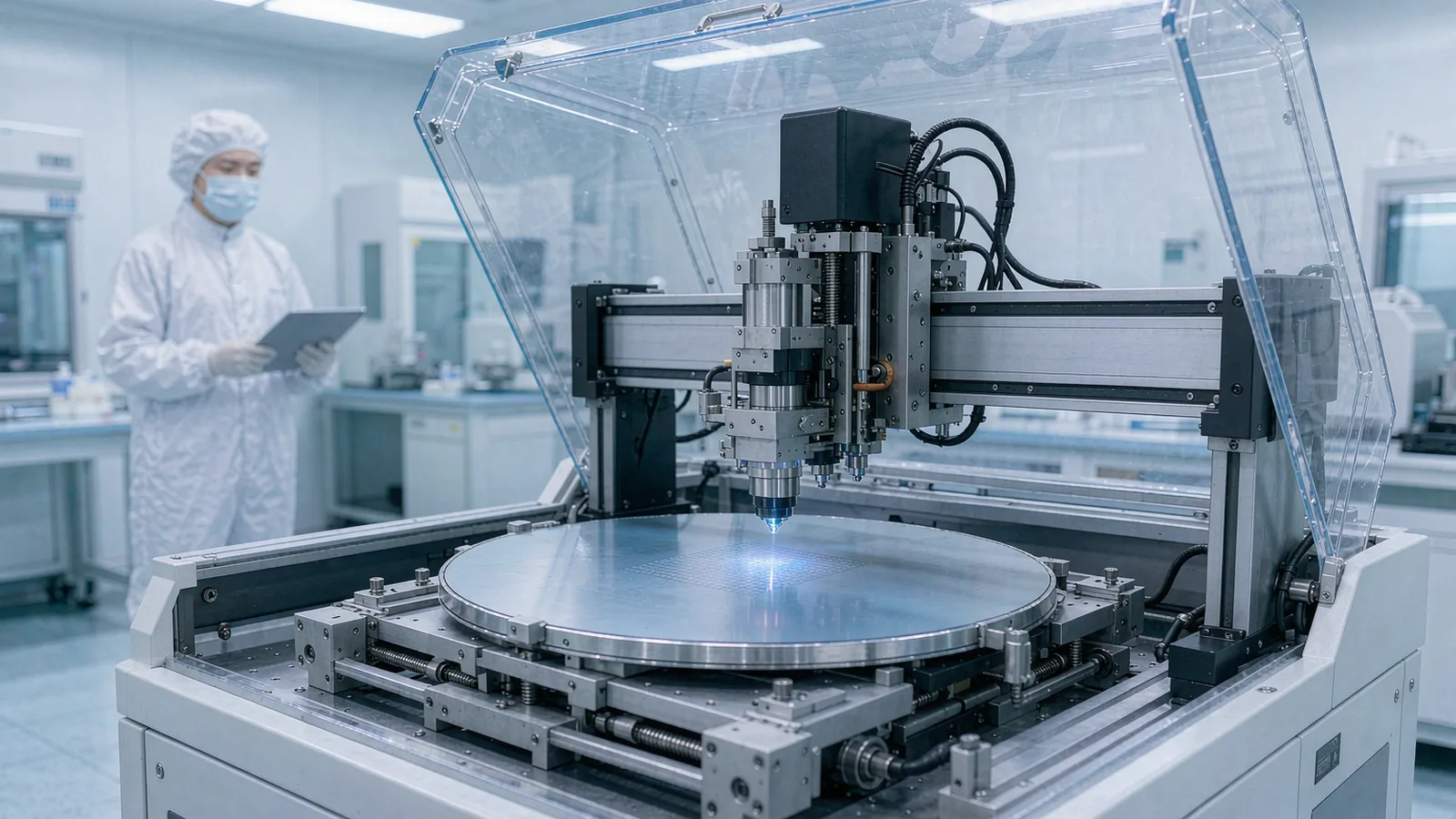
In maskless lithography the exposure time is paid per feature rather than shared through a mask, so writing time scales with total pattern complexity: exposure area, address grid density, dose, writing mode and stage dynamics. A tool that patterns one square centimeter of dense features may take an hour; the same tool blanketing the same area at sparse coverage takes minutes. Estimating throughput therefore means decomposing the job, not reading a single figure from a datasheet.
The practical levers are, in order of impact: expose only the fields that carry features, choose the coarsest writing mode and address grid that still meet the geometry rules, use the minimum dose that develops correctly, and keep the stage continuously writing by sensible field sequencing. Plans that ignore these levers produce jobs measured in shifts; plans that apply them routinely fit the same device into hours.
ENGINEERING CONTEXT
A research team quotes a direct-write tool's headline throughput, books instrument time, and discovers mid-job that the wafer will take three times longer than planned: the pattern's dense layer alone consumes the estimate, dose was set conservatively for a wet process that later optimized, and the exposure area included large fields carrying only a few alignment marks. Direct-write throughput is genuinely job-dependent, which is its strength for prototyping and its trap for scheduling. Without a decomposition of writing time into exposure area, grid density, dose and overhead, capacity planning becomes guesswork, and the tool that looked slower than a mask-based flow on paper often wins in practice once the mask-making lead time is counted honestly.
Discuss your requirement ↗CRITICAL REQUIREMENTS
Separate the layout into layers and fields by feature density, identify minimum feature and critical dimension targets, and quantify the area that actually carries pattern versus area that is nominally exposed.
Match writing mode, address grid and pixel or beam parameters to each layer's geometry rules, using coarser settings where CD and overlay targets allow.
Establish the minimum correct dose per resist and wavelength through a dose-matrix experiment, and record it per process recipe, since dose multiplies directly into writing time.
Plan field order, autofocus and alignment events, stage repositioning and substrate handling as part of the estimate, so the quoted time includes the real overhead of the run.
BUYER MATRIX
Give every shortlisted supplier the same process definition and request configuration-specific proof.
| Factor | How it enters the time budget | Typical planning error | Effective lever |
|---|---|---|---|
| Exposed area | Time grows with the written area, not the substrate size | Quoting a 100 mm wafer time while the device uses 10% of the area | Expose device fields only; clip or blank empty regions |
| Address grid / pixel density | Finer grids write more addresses per unit area | Applying the finest grid to all layers | Match grid to CD per layer; coarse layers at coarse grid |
| Dose | Dwell or scan rate scales inversely with dose | Over-dosing 'for safety' after a marginal first develop | Dose-matrix calibration; keep the proven minimum |
| Writing mode | Higher-resolution modes trade speed for fidelity | Using the highest-resolution mode for non-critical layers | Assign modes per layer: critical CD vs bulk geometry |
| Overhead | Alignment, autofocus, stage moves and handling add fixed time | Omitting overhead from short-field jobs with many fields | Sequence fields to minimize moves; batch by layer; include overhead in the estimate |
A mask-based exposure shares its cost across every die through a mask written once; a direct-write tool pays for every feature at every write. The time budget therefore decomposes into a small set of terms. The first is pure exposure: the beam or spatial light modulator writes addresses on a grid, and the number of addresses times the dwell per address, divided by the effective scan rate, gives the on-target time. Dense layers with fine geometry dominate this term. The second is stage motion between fields and the settling that follows; the third is metrology overhead, autofocus events and alignment measurements, each of which carries a fixed cost multiplied by how often the job invokes it. The fourth is handling: substrate load, pre-alignment, development breaks between layers for multi-layer processes.
Two consequences follow. Small substrates with many small fields can surprise: the per-field overhead of autofocus and alignment, multiplied across hundreds of fields, can exceed the writing time itself, so field merging and sensible sequencing are as important as raw scan speed. Conversely, a large substrate with a sparse pattern can be fast if the tool supports writing only where features exist, which is one of the quiet advantages of direct-write for research: the time follows the pattern, not the wafer.
This decomposition is also why datasheet throughput numbers must be read with care. A figure quoted for a specific pattern, area and dose is a reference point, not a promise; the honest planning method is to rebuild the estimate for the actual job using the tool's parameter set, and SENFU's application engineering provides exactly this exercise for its ZML-series tools against a customer's layout and process.
Dose is the multiplier most often left out of early estimates. Writing time scales roughly with the dose delivered: a pattern written at 150 percent of the necessary exposure takes half again as long, across every layer it touches. Because dose requirements depend on resist, thickness, substrate reflectivity and wavelength, the disciplined approach is a dose-matrix experiment early in process development: a ladder of exposures across the working range, developed and inspected, with the minimum dose that produces the target CD with process margin recorded in the recipe. Repeating that calibration when resist batches or process steps change keeps the recipe, and therefore the schedule, honest.
Resolution settings trade directly against speed. Finer address grids and higher-resolution writing modes increase the number of addresses and typically reduce scan rate; they should be spent where the pattern demands them. A practical job assigns settings per layer: the gate or waveguide layer receives the finest mode and grid, while bond pads, coarse test structures and bulk cavities receive the fastest setting that meets their geometry rules. On multi-layer devices this layer assignment alone can cut total writing time substantially, because the coarse layers usually dominate area.
Proximity and heating effects interact with the same trade. Dense regions may need dose modulation or corrections to hold CD, and very fast writing of high-dose regions raises thermal considerations in the resist. These are process questions to settle during development, but they belong in the throughput conversation because the corrections change both dose and mode, and therefore time. Planning that treats resolution, dose and fidelity as one coupled budget produces schedules that survive contact with the process.
Rebuild the estimate for each job rather than quoting a single tool figure.
Direct-write scheduling rewards batching by layer and thinking in fields. Run all wafers of the same layer back to back to amortize alignment setup; order fields to keep stage travel short and autofocus events predictable; and group jobs with similar writing modes so the tool avoids repeated reconfiguration. For prototyping workflows, the mask-free advantage usually dominates: the schedule cost of a design iteration is a writing job, not a mask order with its lead time and amendment cost, so total development time can be shorter even where the raw exposure is slower than a mask aligner.
Capacity planning should account for the split between engineering time and tool time. A mask-based flow moves cost and risk into mask procurement; a direct-write flow moves them into exposure hours. That makes the tool's utilization the scarce resource, and it justifies investment in the estimation method above: a lab that can predict writing time per job schedules confidently, books the right windows, and avoids the half-finished wafer that blocks the instrument. It also clarifies the crossover against mask-based production: at low volumes and changing designs, direct-write wins; at very high volumes of a frozen design, the mask amortizes. Between those poles, the decision is pattern-dependent and best made with real decomposed estimates for the actual layouts.
SENFU supports this planning directly. For each ZML-series configuration, application engineering can review a customer's GDSII or equivalent layout data, propose per-layer writing settings, and provide a writing-time estimate at stated dose and mode, so instrument scheduling and process development proceed from numbers rather than impressions. The result is a throughput discussion grounded in the actual pattern, which is the only level at which direct-write throughput is a meaningful quantity.
Treat the first run of any new job as a calibration of the estimate, not only of the resist. Record actual writing time per layer against the prediction, and the split between exposure, stage and overhead, using the tool's job log. Divergence points at specific modeling errors: overhead heavier than assumed on many-field jobs, dose higher than the recipe after process changes, or a writing mode left at a fine setting on a coarse layer. Each correction feeds the next estimate, and within a few cycles a lab accumulates a small library of measured jobs that makes future scheduling reliable.
The same records serve procurement and utilization reporting. A tool whose logged writing time per job is tracked against plan exposes drift, whether from process creep, degraded source output requiring higher dose, or mechanical settling time that maintenance should address. Throughput, in other words, is not only a selection question at purchase; it is an operating metric with the same standing as overlay and CD.
Document each job with the settings that produced it: layer, mode, grid, dose, area, measured time. Over a development program this log becomes the lab's own reference for what patterns cost, and it is the evidence base for decisions about whether a given device belongs on the direct-write tool, on a mask-based instrument, or split between them. SENFU's application engineering can help establish this logging discipline and review job data during process ramp-up.
CONCLUSION
Maskless lithography trades mask cost and lead time for exposure hours, and the size of that trade is decided by how jobs are planned: expose only patterned fields, match writing mode and address grid to each layer's geometry rules, hold dose at its calibrated minimum, sequence fields sensibly, and account for overhead honestly. Labs that estimate this way schedule with confidence; labs that quote a datasheet figure do not.
For a SENFU throughput review, send the layout data, substrate and process parameters, and the target schedule. SENFU application engineering can provide a decomposed writing-time estimate per layer, propose settings that meet the geometry rules at the lowest time cost, and support the job logging that keeps future estimates calibrated against the machine.
SOLUTION ROUTES
EVIDENCE CHECKLIST
FAQ
Decompose the job: per layer, take the exposed area after clipping empty regions, multiply by address density for the chosen grid and mode, divide by the tool's effective scan rate at the calibrated dose, then add per-field overhead for alignment, autofocus and stage moves plus handling. Most tools or their suppliers provide parameter tables for this calculation; SENFU offers the estimate as an application review against customer layout data.
Datasheet figures are quoted for a reference pattern, area and dose. Real jobs differ in density, grid, dose and overhead. The usual culprits are the finest writing mode applied to all layers, a conservative dose, and per-field overhead on many small fields. Decompose the job to find which term exceeded the reference.
Generally yes, because finer address grids and higher-resolution modes write more addresses per area and often scan slower. The planning task is to spend resolution only where geometry rules demand it: critical CD layers at fine settings, bulk and coarse layers at the fastest compliant settings. Per-layer assignment typically saves a large fraction of total time on multi-layer devices.
Dose scales nearly one-to-one into exposure time, so a pattern written at twice the necessary dose takes about twice as long on the exposed area. A dose-matrix calibration that establishes the minimum dose with process margin, kept in the recipe, is one of the cheapest throughput improvements available.
For prototyping, low volumes and changing designs, direct-write usually wins on total schedule because a design iteration costs a writing job instead of a mask order with its lead time. At high volumes of a frozen design, mask amortization reverses the result. The crossover is pattern- and volume-dependent, and is best evaluated with decomposed time estimates for the actual layouts.
Send the layout data in a standard exchange format, the substrate and layer list, resist and wavelength, and any CD or overlay constraints per layer. SENFU application engineering returns a per-layer estimate at stated mode, grid and dose, with the assumptions documented so your schedule can be maintained as the process evolves.
AUTHORITATIVE SOURCES
TECHNICAL REVIEW
Send the application, critical parameters and any drawing or process information available.
Discuss your application ↗