
Exposure characterization
Map what the encoder actually sees: splash direction and volume, coolant type and concentration, mist, chip impact, dust, washdown chemicals, temperature and humidity swings, and dwell time between cycles.
TECHNOLOGY / ENCODER ENVIRONMENTAL ENGINEERING
Match optical encoder sealing to real machine conditions: what IP ratings do and do not promise, coolant mist, dust, washdown, pressure differentials, condensation and the installation details that decide sealing reliability.
Published
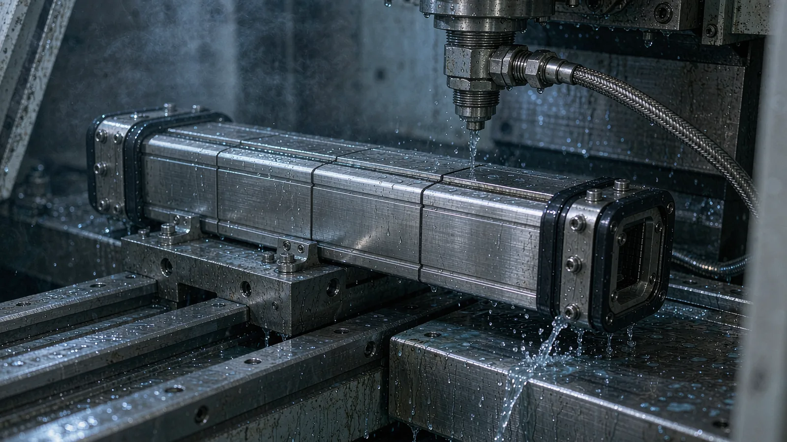
DIRECT ANSWER
An IP rating tells you how well an enclosure resists solids and water under standardized test conditions, not how the encoder will behave in your machine. For optical encoders the practical decision is threefold: choose a sealing class matched to the exposure (splashing coolant, mist, dust, washdown), then engineer the installation so that sealing is not defeated by cable entry, mounting joints, thermal cycling and pressure differences.
As a rule of orientation, IP54-type protection suits enclosed machine interiors with dust and light splash; IP64- to IP66-type encoders suit direct coolant exposure on machining centers; IP67-type designs suit washdown or intermittent immersion. Whatever the class, the weak points are almost always the interfaces the rating does not cover: cable glands, connector shells, scale end caps and the boundary between the scale's mounting surface and the readhead. Specify them together, and verify with the machine running, not with a datasheet alone.
ENGINEERING CONTEXT
An encoder can be selected with the right resolution and installed with correct alignment, and still fail within months because coolant mist condensed inside the scale tube, cutting fluid entered through a mis-fitted gland, or dust accumulated on the scale surface the sealing scheme never intended to expose. The difficulty is that ingress failures are progressive and intermittent: they show up as diminishing signal margin, occasional count errors, or a readhead that reads cleanly on Monday mornings but errors after a hot afternoon cycle. Teams then replace electronics that were never the problem. The root cause is usually a mismatch between the nominal IP class and the machine's actual exposure, or an installation that defeats a correct rating at a single unprotected interface.
Discuss your requirement ↗CRITICAL REQUIREMENTS
Map what the encoder actually sees: splash direction and volume, coolant type and concentration, mist, chip impact, dust, washdown chemicals, temperature and humidity swings, and dwell time between cycles.
Choose the encoder's protection class against the exposure and identify every ingress path the class does not cover: cable entry, connectors, mounting joints, end caps and breathing through temperature cycling.
Specify cable gland types and strain relief, connector orientation, surface finish and flatness of mounting interfaces, sealant use, and protective covers or air purging where the environment demands them.
Record signal margin, error counters and inspection of sealed interfaces after a defined period of production machining, not only at commissioning, so degradation is caught before failure.
BUYER MATRIX
Give every shortlisted supplier the same process definition and request configuration-specific proof.
| Protection class (typical) | Machine environment | What it protects against | Residual risk to engineer around |
|---|---|---|---|
| IP54-type | Enclosed machine interiors, general automation, light dust and indirect splash | Dust deposition in harmful quantities, water splashes from any direction | Direct coolant jets, washdown, sustained mist condensation on cold electronics |
| IP64–IP66-type | Machining centers and turning machines with coolant splash and mist exposure | Total dust ingress, powerful water jets from any direction (IP66) | High-pressure washdown jets beyond supplier specification, immersion, ingress at cable gland or connector interfaces |
| IP67-type | Washdown environments, food and packaging machinery, intermittent immersion risk | Temporary immersion under defined depth and duration | Chemical attack of seals and jackets, thermal cycling breathing, repeated pressure differential across seals |
| IP69K-type designs | High-pressure, high-temperature washdown | Close-range steam-jet cleaning | Seal aging from repeated thermal shock, chemical compatibility of housing and cable materials |
The IP code defined in IEC 60529 classifies an enclosure against ingress of solids and water using standardized laboratory tests: dust chambers, drip trays, oscillating spray arms, jets of defined pressure and flow, and for higher classes, immersion at defined depth and duration. The two digits answer two narrow questions. The first digit concerns solid objects and dust; the second concerns water. A rating of IP67 means dust-tight by test and resistant to temporary immersion by test. It does not mean the encoder is immune to the way your machine applies coolant, the chemistry in your cutting fluid, or the thermal cycling between a morning cold start and an afternoon production peak.
Three practical consequences follow. First, ratings are additive only in the sense tested: a device rated for immersion is also rated for jets, but the reverse is not implied, and neither class says anything about oil, emulsion, or aggressive cleaning agents, which are governed by separate chemical compatibility considerations. Second, the rating applies to the enclosure as tested, with intact seals and proper closures; the moment a connector is mated at an angle, a gland is overtightened or undertightened, or a cable jacket diameter is outside the gland's clamping range, the tested seal no longer exists. Third, ratings are static. They do not describe the pumping action that thermal cycling produces across a sealed housing as air inside expands and contracts, drawing in humid outside air through any imperfect seal and depositing condensation on the coldest internal surface.
This is why experienced specifiers treat the IP class as the beginning of the sealing discussion, not the end. The class filters the candidate encoders; the machine's actual exposure profile and the installation detail decide whether sealing survives in service.
Start by writing down the exposure, zone by zone on the machine. A machining center's spindle-area guideways see direct coolant flood, chip impact and mist; the column interior behind covers sees only suspended mist and dust; the electrical cabinet sees neither. An encoder on each of those three axes faces a different problem despite being the same product family. Direct flood and chip impact call for an encoder with hard sealing surfaces, robust scale housing and, often, a deflecting cover or way wiper arrangement; mist zones call for attention to condensation and breathing; protected zones can use lighter sealing classes with correspondingly smaller envelopes and lower cost.
Coolant chemistry matters as much as quantity. Water-miscible emulsions, neat oils and synthetic coolants differ in their effect on seal materials, cable jackets and adhesive systems. Suppliers publish compatibility tables for seal compounds and jacket materials; a seal that swells in neat oil may be unaffected by emulsion and vice versa. Where washdown with alkaline or disinfectant solutions is involved, as in food and pharmaceutical machinery, both the housing materials and the cable must be checked against the cleaning regime, and the IP69K-style steam-jet rating becomes relevant rather than a simple immersion class.
Temperature and humidity define the condensation problem. An encoder that runs cold overnight in an unheated workshop, then meets warm humid air at shift start, will condense moisture on its coldest internal surfaces regardless of IP class if humid air was ever able to enter. The engineering responses are to minimize air exchange through better sealing and glands, to avoid creating preferential breathing paths through connectors routed vertically above the housing, and where conditions are severe, to select sealed designs with desiccant or purged-air options that the supplier offers for exactly this purpose.
Reduce the decision to a short list of verifiable items rather than a single class number.
Field experience consistently locates sealing failures at interfaces, not in the body of a properly specified encoder. The cable entry is first among them. A gland must match the jacket diameter within its clamping range, be torqued per the supplier's specification, and maintain sealing through the cable chain's motion, which argues for chain-rated cable with a round, abrasion-resistant jacket and against any improvised grommet. Connectorized entries must seat fully and orient the shell so that water running down the cable does not wick into the mating face; drip loops and downward-facing entries are simple geometry that prevents the majority of moisture complaints in splash zones.
Mounting interfaces are the second ingress path. The boundary between a scale housing and its mounting surface, and between a cover and its rail, seals only over the stated surface finish and flatness. Machining burrs, sealant squeezed into a gap it cannot bridge, or a mounting rail bolted onto an unmachined casting face create channels that a jet test would never reveal but that a machine's real vibration and thermal cycling will exploit. Where protective covers or bellows are part of the sealing concept, their end fittings and clamps belong in the same inspection as the encoder itself.
The third path is time. Seals age; gaskets take a set; vibration works fasteners loose. A sealing concept specified on the drawing should include a re-check interval: signal margin recorded at commissioning, then sampled at planned maintenance, with the signal amplitude and error counters compared against the baseline. A slow decline in signal margin on a scale that receives mist exposure is the early warning of film formation on the scale surface or moisture in the optics, and it arrives weeks or months before an actual position error. SENFU's application engineering reviews sealing and installation plans for the intended environment and can advise on cover arrangements, gland selection and signal-margin baselining during commissioning so that degradation is measurable rather than invisible.
The verification step that matters is not the bench test at standstill but the inspection after representative production. Define an acceptance record at commissioning: signal margin per axis, error counters, photographs of gland and connector installation, and the exposure assumptions per zone. Then define a first re-inspection at an interval matched to the environment, for example after the first weeks of coolant machining, and compare the recorded signal margin against baseline. Optical encoders give clear physical evidence when sealing begins to fail: reduced signal amplitude, elevated internal scattering showing as degraded interpolation margin, or error flags correlated with coolant-on cycles.
Escalate findings by ingress path rather than by part swap. A margin loss that appears only after coolant-on periods points at the scale's own sealing or a missing cover; a loss independent of machine state points at cable entry or connector; a loss accompanied by visible deposits at the mounting joint points at the installation interface. Correcting the path, re-baselining the signal, and recording the change turns sealing from a hope into a maintained property of the machine.
SENFU supports this verification with configuration-specific documentation: the protection class of each encoder model stated against the IEC 60529 definitions, environmental application notes for coolant, mist and washdown exposure, and commissioning records designed to capture the signal baselines that make later comparisons meaningful. The result is an encoder installation whose sealing is documented, inspectable and maintainable over the machine's life, rather than a rating number inherited from a datasheet.
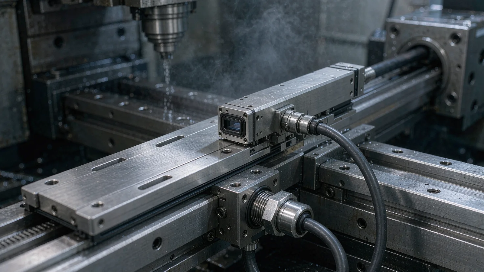
CONCLUSION
IP ratings are a controlled-test classification and a useful first filter, but environmental reliability comes from the system around them: an exposure map per axis, chemical compatibility of every wetted material, ingress paths engineered outside the rating, and a verification record with signal baselines that reveal degradation early. Machines fail sealing at glands, connectors and mounting joints far more often than at the encoder body.
For a SENFU environmental review, send the machine zones and exposure conditions, coolant or cleaning specifications, the candidate encoder configuration and the installation drawing. SENFU application engineering can confirm the sealing approach, recommend protective measures, and define the commissioning baselines that keep the installation verifiable over its service life.
SOLUTION ROUTES
EVIDENCE CHECKLIST
FAQ
Not necessarily. The higher class costs envelope, price and sometimes performance, and it still does not cover the interfaces where most failures occur: glands, connectors and mounting joints. Select the class against a written exposure map, and invest the remaining effort in installation detail and verification. A well-installed IP64-type unit in a splash zone often outlasts a poorly glanded IP67 unit.
Thermal cycling causes the air inside the housing to expand and contract, drawing humid outside air through any imperfect seal or connector interface. When the housing then cools, moisture condenses on the coldest internal surface. The remedy is better sealing at entry points, avoiding upward-facing vertical connector runs, and where conditions are severe, supplier options such as desiccant or purged housings.
Zones with direct flood and chip impact typically call for IP64- to IP66-type sealing plus mechanical protection such as covers or deflectors; mist-only zones may suit lower classes with condensation management. The decision must also account for coolant chemistry against seal and jacket materials. Ask the encoder supplier to confirm the class against your written exposure map rather than choosing from the number alone.
Only within the supplier's installation instructions. Enclosures are tested as complete systems; added sealant can block intended drainage or breathing paths, trap moisture against optics, and complicate service. Use specified glands, seals and covers, and where the environment exceeds the product's design envelope, involve the supplier rather than improvising.
Record signal amplitude and error counters at commissioning and sample them at planned maintenance. A gradual decline in signal margin, especially when correlated with coolant-on periods or humidity events, is the early indicator of film formation or moisture ingress. Catching that trend allows a planned intervention instead of an unplanned stop.
Send the per-axis exposure map (flood, splash, mist, dust, washdown, temperature and humidity ranges), the coolant or cleaning chemistry, the candidate encoder model and the installation drawing with gland and connector detail. SENFU can confirm the sealing concept, recommend protective measures and define the commissioning baseline for later verification.
AUTHORITATIVE SOURCES
TECHNICAL REVIEW
Send the application, critical parameters and any drawing or process information available.
Discuss your application ↗