
Qualified mounting surfaces
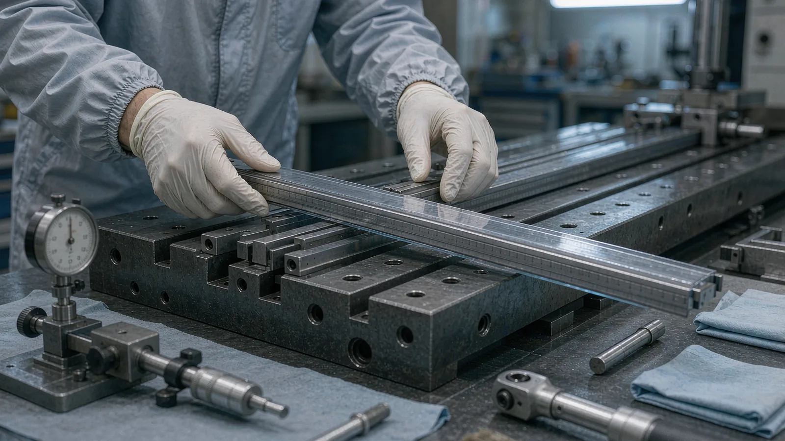
Datum faces with specified flatness, parallelism and cleanliness so the scale and readhead inherit geometry from controlled references, not from assembly luck.
TECHNOLOGY / ENCODER INSTALLATION
Identify and correct linear encoder installation errors: Abbe offset, mounting-surface flatness, readhead gap and parallelism, thermal expansion compensation and acceptance verification methods.
Published
DIRECT ANSWER
Most linear encoder problems are installation problems, not sensor failures. Position error enters through Abbe offsets, non-flat mounting surfaces, wrong readhead gap or tilt, scale-to-guide misalignment and uncompensated thermal expansion between scale and workpiece. Each mechanism has a distinct signature, so installation should be verified with defined measurements — gap, parallelism, flatness and travel-referred error maps — rather than with a signal-strength check alone.
ENGINEERING CONTEXT
An encoder's data sheet describes a calibrated scale and readhead, but the numbers only survive installation if the mechanics cooperate. A scale mounted on a warped surface takes on that warp; a readhead set at the wrong gap loses signal margin precisely when the axis moves fastest; an offset between the measurement line and the point of interest converts every angular guide error into linear position error. Because these contributions mix with servo tuning and environment, teams often chase electrical causes for what are mechanical installation defects. The cure is a structured installation procedure with measured acceptance criteria at each step.
Discuss your requirement ↗CRITICAL REQUIREMENTS
Datum faces with specified flatness, parallelism and cleanliness so the scale and readhead inherit geometry from controlled references, not from assembly luck.
Recorded gap, yaw, pitch and roll within the manufacturer's tolerance window, plus Abbe offsets documented in the machine error budget.
A defined scale-material and expansion-compensation plan, and an acceptance test that refers error to the workpiece over full travel.
BUYER MATRIX
Give every shortlisted supplier the same process definition and request configuration-specific proof.
| Error source | Typical symptom | Verification method |
|---|---|---|
| Abbe offset | Position error grows with guide yaw or pitch; error reverses with travel direction of the angular component | Measure offsets from scale line to tool point; combine with angular error data over travel |
| Mounting-surface flatness | Periodic error correlated with position; local scale-to-readhead gap variation | Map datum flatness before mounting; check gap along full travel |
| Incorrect gap or tilt | Reduced signal amplitude or degraded quadrature balance, worst at speed or travel extremes | Verify gap at both travel ends and mid-travel with feeler or witness method |
| Scale-to-guide misalignment | Cumulative error increasing along travel; elevated bearing or readhead wear over time | Indicate scale datum parallel to guide axis at several points along travel |
| Thermal expansion mismatch | Error and scale drift with machine temperature; error differs between cold start and warm state | Compare error maps cold and warm; log scale and structure temperatures |
| Datum or reference offset | Consistent shift or skew after homing; error constant along travel | Check reference mark location and homing repeatability at fixed conditions |
A linear encoder measures position along one line: the effective scale axis. Everything the machine cares about — the tool center point, the wafer chuck, the workpiece datum — sits elsewhere in space. Between the scale reading and the useful position stand the guide geometry, the structural loop, the mounting interface and the temperature field. Installation quality decides how quietly those elements pass their errors into the measurement.
The useful mental model is a chain of transfers. Scale accuracy and interpolation quality are the encoder's own contribution; installation geometry decides how much additional error the mechanics inject. Flatness errors in the mounting surface transfer directly into scale shape, because the scale conforms to its datum. Angular errors of the guided carriage transfer into position error wherever the measurement line and the point of interest do not coincide. Thermal gradients transfer into differential expansion between scale and structure.
This chain explains a familiar observation: two machines with identical encoders can behave very differently. The difference is rarely the sensor; it is whether the installation was treated as part of the metrology or as a fitting task. The sections below walk through the four dominant transfer mechanisms and how to verify each one.
Abbe's principle states that measurement error from an angular motion equals the product of that angular error and the distance between the measurement line and the line through the point of interest. On a linear stage, if the readhead sits 100 mm below the tool point and the carriage yaws by 10 arc-seconds, the induced position error at the tool is roughly 100 mm × sin(10″) ≈ 4.8 µm — often far larger than the encoder's own scale error.
Two design responses exist, and they are not alternatives. The first is to minimize the offset: place the scale at the height of the working point, on the axis where angular errors are smallest, typically inside the structural loop near the guide midpoint. The second is to measure and compensate: record the offsets, measure angular errors over travel with a straightedge, autocollimator or laser interferometer angular optics, and compute the contribution into the machine error budget. The VIM's distinction between the quantity intended to be measured and the quantity actually measured is exactly the distinction between tool-point position and scale indication.
In debugging, Abbe error has a signature: position error that correlates with guide yaw or pitch rather than with scale position itself, and that changes when payload height changes. If an error map changes sign or magnitude after a heavier workpiece is mounted, suspect angular deflection acting through an offset before suspecting the encoder.
The scale datum and readhead bracket turn the machine structure into part of the measuring instrument. If the scale mounting face deviates from flatness, the scale follows it, adding a position error with the same spatial period as the defect. Cleaning, burr removal and verifying flatness within the manufacturer's stated tolerance cost minutes; discovering the same defect later as a mysterious periodic error costs days. Adhesive-mounted tapes additionally demand controlled surface finish and cleanliness, because bond-line thickness variations become geometry variations.
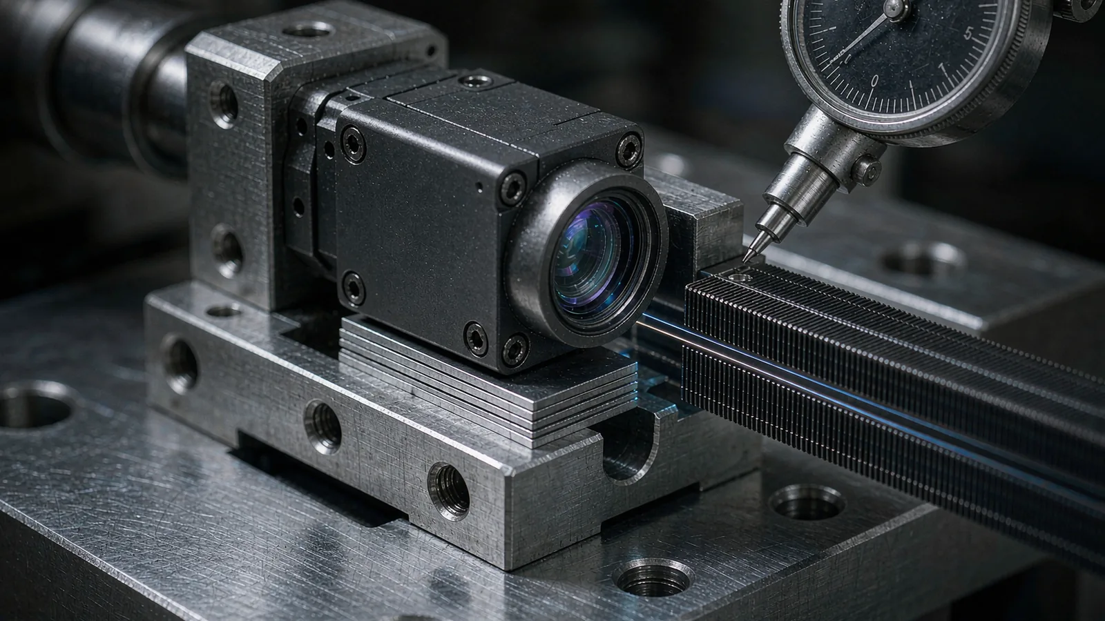
The readhead gap deserves equal discipline. Every optical encoder has a nominal sensing gap with a tolerance; running near the tolerance edge sacrifices signal amplitude and, with it, interpolation quality and contamination margin. Verify the gap at both ends of travel and at mid-travel, because bracket compliance and datum tilt make the gap a function of position. A gap that changes along travel indicates either a tilted bracket or a warped datum — both fixable before the axis ever runs a process.
Yaw, pitch and roll of the readhead relative to the scale matter as much as the gap, since tilt redistributes optical signal between quadrature channels. The practical procedure is short: set the nominal gap with the manufacturer's gauge or feeler method, tighten fasteners in the specified sequence, then confirm the signal-conditioning indicators (amplitude, quadrature balance or warning output) across full travel. Record the values; they become the reference for future service checks.
Every scale material has a coefficient of thermal expansion, and so does the machine structure it is bolted to. When those coefficients differ, temperature changes make the scale and the structure grow at different rates, and the indicated position drifts relative to the physical geometry. A steel scale on an aluminum base, for example, sees an expansion mismatch of roughly 12 ppm/K against 23 ppm/K — about 11 µm per meter of travel per kelvin, which is significant for micron-class tolerances.
Compensation strategies follow the error budget. Glass scales with low expansion coefficients favor dimensional stability of the measurement line itself. Steel-tape scales can match structure expansion, keeping differential growth small at the cost of stronger coupling to structure temperature. Controller-level compensation adds a temperature-dependent correction using measured machine temperatures; it works only if the sensor locations represent the actual thermal behavior, which should be validated, not assumed.
The debugging signature of thermal error is slow drift correlated with machine state: error maps that differ between cold start and warm operation, or repeatability that improves after a fixed warm-up cycle. Capture error maps at defined thermal states, log scale and structure temperatures during testing, and treat any compensation constant as a configuration item under change control, as developed in the thermal error budget guide.
Installation acceptance should mirror the error sources, not just the data sheet. A practical sequence: verify datum flatness and cleanliness before mounting; set and record gap, yaw, pitch and roll at multiple travel positions; confirm signal-quality indicators across full travel; then run a bidirectional positioning test per ISO 230-2 over full travel and compare the error map against the encoder's stated scale accuracy. The difference between the two maps is the installation's contribution, and it should match the error budget that predicted it.
When an installed axis misbehaves, work the signatures in order. Error repeating with travel period points to scale shape or mounting periodicity. Error correlated with direction points to reversal losses and backlash rather than the encoder. Error correlated with position along travel points to scale misalignment with the guide or uncompensated linear error. Error correlated with temperature points to expansion mismatch. Error correlated with speed points to interpolation bandwidth or signal quality, not installation.
Close the loop with records. Keep the signed gap and alignment sheet, the commissioning error map and the thermal state at which it was taken. Every later anomaly gets compared against that baseline, which turns encoder troubleshooting from archaeology into a two-point comparison.
CONCLUSION
Linear encoder accuracy is decided as much by the mounting face, the gap setting, the Abbe offset and the thermal design as by the scale itself. Each of these error sources has a recognizable signature, and each can be verified with a short, defined measurement during installation — flatness mapping, gap checks along travel, angular error measurement, and cold-versus-warm error maps. A structured installation procedure converts unknown assembly variation into recorded, budgeted geometry.
For a SENFU review, provide the axis travel, scale type and length, mounting concept, readhead envelope, operating temperature range and the positioning tolerances to be achieved. SENFU can map those inputs to source-backed encoder configurations, state the installation tolerances that must be held and identify which acceptance measurements will close the loop before the machine ships.
SOLUTION ROUTES
EVIDENCE CHECKLIST
FAQ
Abbe error is position error caused by angular motion of the stage acting through the distance between the measurement line and the point of interest. For example, a 10 arc-second yaw with a 100 mm offset induces roughly 4.8 µm of error at the tool point — often exceeding the encoder's own scale error. Minimize the offset and compensate the remainder from measured angular data.
Set the nominal gap with the manufacturer's gauge or feeler method, then verify it at both ends of travel and at mid-travel, since bracket tilt and datum warpage make the gap position-dependent. Confirm signal-quality indicators remain within specification across the full travel and record the values.
Differential thermal expansion between the scale and the machine structure, or thermal distortion of the structure itself, shifts the measurement geometry as temperatures rise. Compare error maps at defined thermal states while logging scale and structure temperatures, then apply matched-material selection or controller compensation validated against measurements.
Error repeating with travel period suggests scale shape or mounting periodicity; error increasing along travel suggests scale-to-guide misalignment; error correlated with temperature suggests expansion mismatch; error correlated with speed suggests signal or interpolation issues. Direction-dependent error is usually reversal or backlash in the mechanics, not the encoder.
Datum verification before mounting, recorded gap and angular alignment at multiple travel positions, signal-quality checks across travel, and a bidirectional positioning test per ISO 230-2 whose error map is compared against the stated scale accuracy, with the measurement method, thermal state and uncertainty documented.
AUTHORITATIVE SOURCES
TECHNICAL REVIEW
Send the application, critical parameters and any drawing or process information available.
Discuss your application ↗