
A measurement method with known uncertainty
Diagonal measurements from a laser interferometer or comparable traceable instrument, with the measurement uncertainty stated and environmental conditions recorded during the run.
TECHNOLOGY / VOLUMETRIC METROLOGY
Passing every single-axis accuracy test can still leave a multi-axis stage hundreds of micrometres off target in the corners of its workspace. This guide explains volumetric error, the ISO 230-6 diagonal test, how to isolate the error sources behind the diagonals, and how to build and verify a compensation model that holds.
Published
DIRECT ANSWER
Volumetric error measurement answers a question single-axis tests cannot: when the stage is commanded to an arbitrary X, Y and Z position, how far is the true tool point from the commanded point in three-dimensional space? A stage can meet its per-axis positioning, straightness and angular specifications individually and still show a much larger error in the corners of the workspace, because the errors combine vectorially and Abbe offsets amplify angular components along the diagonal.
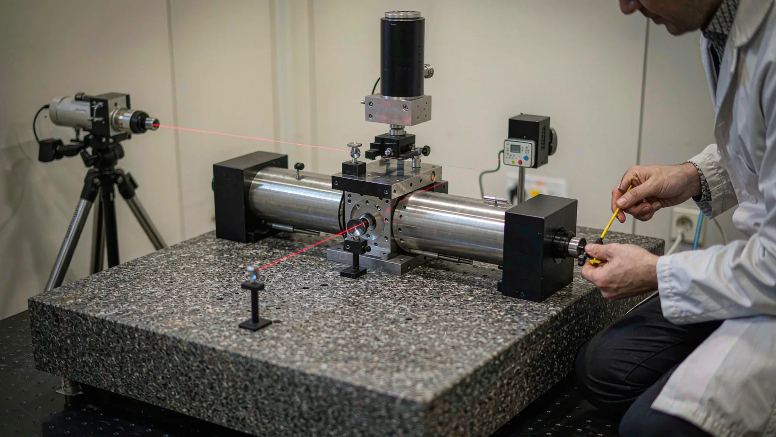
The standard method is the body diagonal displacement test of ISO 230-6 (with the related ASME B5.57 approach): the laser interferometer measures displacement along four body diagonals, in both directions, while the axes move simultaneously. The diagonals reveal the combined effect of positioning, straightness, squareness and angular errors, but they do not identify the sources by themselves. A practical workflow therefore pairs the diagonal test with targeted single-axis measurements, builds a parametric error model, applies compensation, and then re-runs the diagonals to prove the reduction.
ENGINEERING CONTEXT
A two-axis stage is delivered with per-axis certificates that look excellent: positioning accuracy within a few micrometres on X and Y, straightness and squareness documented, repeatability far inside the specification. Then the first customer process runs a pattern that spans the workspace diagonally, and the overlay or feature placement error at the far corner is several times larger than any certificate value suggests. Nothing in the paperwork was wrong; it simply never measured what the process cares about, which is the error at points in the volume, not along the axes. Multi-axis stages accumulate 21 or more distinct error components - six degrees of freedom per axis plus squareness terms - and their combination at off-axis points is invisible to axis-by-axis acceptance. Diagnosing it after delivery is slow and expensive, which is why the volumetric test belongs in the qualification plan before the machine is accepted.
Discuss your requirement ↗CRITICAL REQUIREMENTS
Diagonal measurements from a laser interferometer or comparable traceable instrument, with the measurement uncertainty stated and environmental conditions recorded during the run.
Targeted single-axis positioning, straightness and angular measurements that let the diagonal results be attributed to specific components instead of remaining an unexplained combined number.
A parametric model of the identified components, so corrections can be loaded into the controller and validated, rather than a lookup table that only fits the test points.
A repeat diagonal test, at the same points and conditions, demonstrating the residual volumetric error against a defined acceptance criterion.
BUYER MATRIX
Give every shortlisted supplier the same process definition and request configuration-specific proof.
| Error component | Signature in the diagonal data | Isolation method | Typical correction |
|---|---|---|---|
| Linear positioning error | A scale-factor-like length change along the diagonal, similar in both directions | Compare with single-axis laser positioning runs on each axis | Pitch or error-map compensation from the single-axis data |
| Straightness and squareness | Diagonal length error that depends on the lateral position of the target point | Paired diagonals on opposing faces, per ISO 230-6, to separate squareness from straightness | Mechanical alignment where practical, then squareness terms in the error model |
| Angular errors (pitch, yaw, roll) | Direction-dependent displacement amplified by Abbe offsets along the diagonal | Autocollimator or electronic level angular runs referenced to the actual tool point | Angular terms in the compensation model, reduced Abbe arm as a design fix |
| Repeatability and noise | Random scatter between repeated runs that exceeds the systematic trend | Repeated diagonal runs at identical settings | Mechanical improvement first; compensation cannot remove random error |
| Thermal drift | A slow monotonic trend across the test rather than a position-dependent pattern | Repeat one diagonal over time; log stage and ambient temperature | Warm-up protocol, environment control, temperature-sensitive model terms |
Every axis of a stage has six geometric error components: one linear along the axis of travel and five parasitic - two straightness, three angular. For a three-axis machine that is eighteen components plus three squareness terms between the axes. Each component alone may be small and well within its datasheet line item, but at a point away from the measurement axes the effects add as vectors. The volumetric error at a target point is the distance between the commanded point and the actual point in space, and it is the quantity that determines pattern placement, feature registration and tool-to-tool matching in real work.
This is why a stage can pass every axis-level acceptance test and still disappoint in use. The certificates describe behaviour along the axes; the process operates in the volume. Planning for volumetric error early also changes procurement: it forces the error budget, the Abbe arm lengths and the feedback selection to be discussed together instead of being discovered as separate problems later.
In the ISO 230-6 method, a laser interferometer measures displacement along a body diagonal of the workspace while all axes move simultaneously along it. Four diagonals are measured - the two on each pair of opposing faces - in both directions, typically with several cycles per direction. The paired diagonals are what give the test its diagnostic power: comparing them separates squareness from straightness effects, because a squareness error changes the lengths of opposing diagonals with opposite signs, while many other components appear with the same sign.
The test has limits that a buyer should understand before writing it into a specification. A single diagonal measurement cannot decompose the error into its components, and some error combinations remain ambiguous even with all four diagonals. The diagonal test is therefore a strong verification instrument - it proves how large the combined error is, before and after compensation - but not a complete diagnostic instrument on its own.
Attribution starts with single-axis data. Positioning error along each axis is measured with the laser in the conventional axis-aligned setup; straightness and the angular components are measured on the same axes with appropriate optics. When these measurements are available, the diagonal results can be reproduced by the error model within its uncertainty, and the residuals become a quality check on the measurements instead of a source of argument. If the model cannot reproduce the diagonals, something in either dataset is wrong - a mounting issue, an Abbe offset that was ignored, or an environment that drifted during the run.
Two practical confounders deserve explicit attention. Random error - repeatability, vibration, servo noise - appears in the diagonals exactly as it appears everywhere else, and no compensation model can remove it; the repeated-run scatter of the diagonal test sets the floor that systematic compensation can reach. Thermal drift mimics a slow systematic error and is best excluded by repeating one diagonal at intervals and logging temperatures, so that a trend attributable to warm-up is not baked into the compensation table.
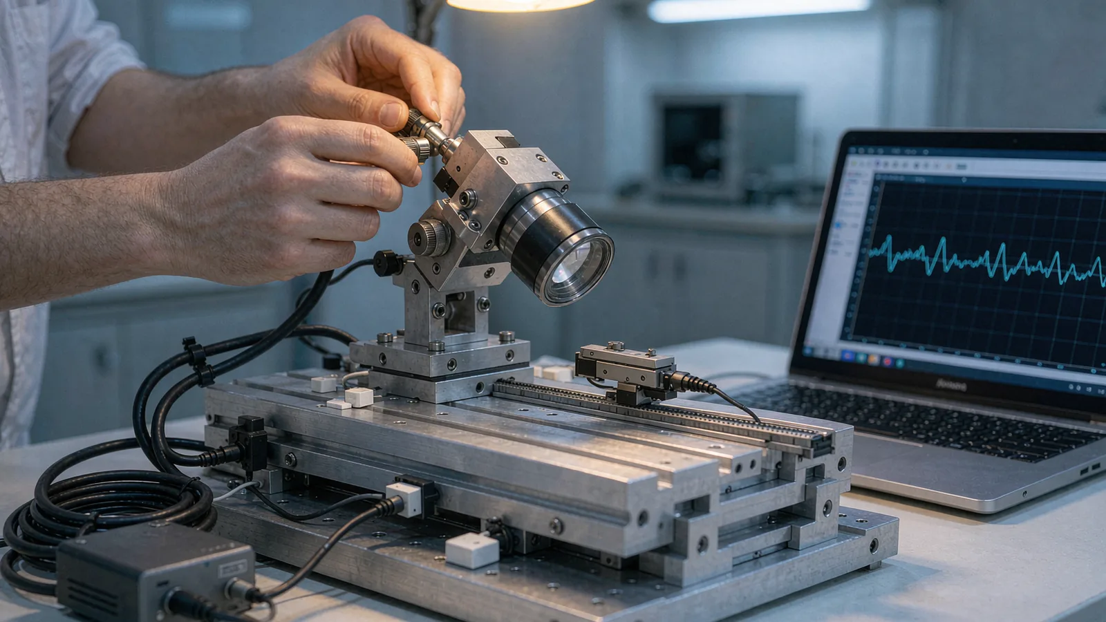
The output of isolation is a parametric model: a small set of geometric parameters - scale factors, straightness polynomials, angular error curves, squareness values - that predict the volumetric error anywhere in the workspace. Loading these parameters into the controller, or applying them through the position feedback loop, corrects the systematic part of the error. A parametric model is strongly preferable to a lookup table that interpolates only the measured test points, because it behaves sensibly between and beyond the points and can be re-fitted when the machine is re-measured.
The quality of the feedback underneath the compensation matters directly. Compensation corrects what the error model describes, based on the encoder readings the controller sees; if the scale itself has uncorrected cyclic or installation errors, the compensation inherits them. This is one of the reasons encoder accuracy, scale installation quality and the error model should be reviewed as one package rather than by separate teams in separate documents.
The acceptance logic is straightforward: run the diagonal test before compensation, record it, apply the model, and run the same test again under the same conditions. The residual volumetric error, together with the repeatability scatter, becomes the acceptance number. What matters for the future is that the measurement is repeatable - same target points, same instrument, same warm-up state - so that the next verification, months later, can be compared against the original without the comparison being dominated by setup differences.
Stages change with use and environment. A sensible maintenance plan re-runs the diagonals at defined intervals or after events that plausibly move the geometry - a collision, a relocation, a major service - and re-fits the model when the residual grows. Treated this way, volumetric error stops being a one-time acceptance hurdle and becomes a monitored property of the machine, which is exactly what processes with tight placement budgets need from their motion supplier.
CONCLUSION
Volumetric error is the quantity real processes experience, and it is invisible to axis-by-axis acceptance. The body diagonal displacement test of ISO 230-6 provides an efficient way to measure it, provided the paired diagonals are interpreted with supporting single-axis data and the method's blind spots are respected.
Isolate the error components, fit a parametric model, compensate through the controller, and prove the result with a repeat diagonal run under matched conditions. With repeatable measurement and periodic re-verification, the residual volumetric error becomes a stable, documented property of the stage - and a firm basis for placement-critical work.
EVIDENCE CHECKLIST
FAQ
No. One diagonal shows the combined error along that line only, and the diagonal test cannot fully decompose the error into its components even with all four diagonals. It is an efficient verification method used together with single-axis measurements, not a substitute for them.
Because per-axis certificates describe behaviour along the axes, while the volumetric error combines positioning, straightness, squareness and angular components as vectors at off-axis points, with angular errors amplified by Abbe offsets. A stage can meet every line item and still show a much larger error in the workspace corners.
Only the systematic part. The repeated-run scatter of the test reflects random error - repeatability, vibration, servo noise - which no model can remove, and thermal drift must be separated before fitting. The scatter floor and the environment log tell you how much of the measured error is actually addressable.
Provide the axis configuration and travel, the Abbe arm lengths or tool-point definition, the environment, and any existing per-axis or diagonal measurement data. SENFU can help define the diagonal test plan, the supporting measurements, the compensation model and the acceptance criterion for the assembled machine.
AUTHORITATIVE SOURCES
TECHNICAL REVIEW
Send the application, critical parameters and any drawing or process information available.
Discuss your application ↗