
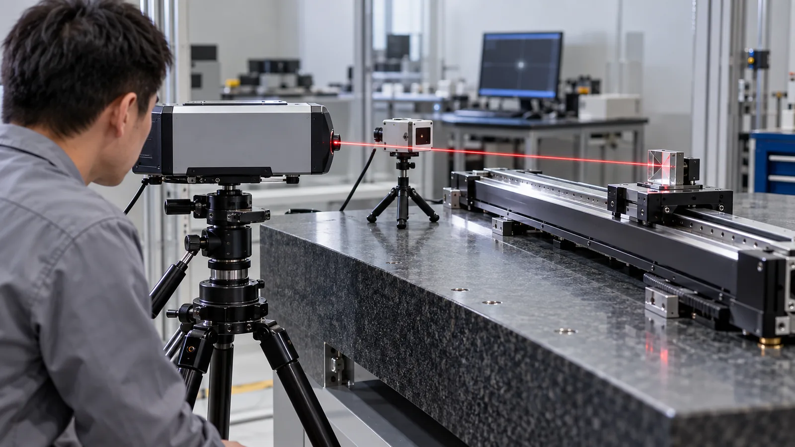
Reference setup
Interferometer optics aligned to the motion axis, minimized deadpath, measurement line matched to the working axis.
TECHNOLOGY / PRECISION STAGE METROLOGY
Verify linear stage positioning accuracy with laser interferometry: setup errors, deadpath, cosine, Abbe, environmental compensation and acceptance criteria.
Published
DIRECT ANSWER
A laser interferometer is the reference instrument for verifying linear stage positioning accuracy because its wavelength is traceable to the meter definition, giving sub-micron agreement over long travel when the setup is correct. The verification value comes from controlling the classical setup errors: align the beam to the motion axis to suppress cosine error, minimize the deadpath between interferometer optics and the reflector start position, place the measurement line as close as possible to the stage's working axis to limit Abbe error, and apply live environmental compensation for air temperature, pressure and humidity.
Run the measurement as a defined protocol: warm up the stage and laser, measure bidirectional positioning error across the stroke at agreed target points with repeated runs, record straightness and angular errors where the acceptance test needs them, and evaluate results against pre-agreed criteria with the raw data retained. A stage that passes with an uncontrolled setup can easily be mis-accepted or mis-rejected by more than the tolerance under test.
ENGINEERING CONTEXT
Stage manufacturers and integrators quote positioning accuracy and repeatability numbers, but the numbers a buyer can defend depend entirely on how they are measured. Laser interferometry is traceable and precise, yet its classical setup errors—cosine error, deadpath error, Abbe error and uncompensated air refractive index—can each contribute more error than the tolerance being verified. Teams must plan the setup, the environmental compensation, the measurement protocol and the acceptance rule before the first measurement, or the verification result is not auditable.
Discuss your requirement ↗CRITICAL REQUIREMENTS
Interferometer optics aligned to the motion axis, minimized deadpath, measurement line matched to the working axis.
Air temperature, pressure and humidity compensation with sensors placed along the beam path, plus stable material temperature.
Target points across the stroke, bidirectional runs, number of repeats and warm-up state specified in advance.
Pre-agreed accuracy and repeatability criteria, uncertainty statement and raw-data retention for audit.
BUYER MATRIX
Give every shortlisted supplier the same process definition and request configuration-specific proof.
| Error source | Behavior | Primary mitigation |
|---|---|---|
| Cosine error | Beam misaligned to the motion axis shortens measured distance by a quadratic term | Align beam to the axis at both ends of travel; residual scales with L·θ²/2 |
| Deadpath error | Air between the interferometer reference and the start position is uncompensated | Minimize the start gap and compensate with measured environment |
| Abbe error | Measurement line offset from the working axis converts angular motion into position error | Place the beam on the working axis or measure the offset and angular error and compensate |
| Wavelength (Edlén) error | Uncompensated air refractive index shifts the effective wavelength | Environmental compensation unit with sensors near the beam path |
| Thermal drift | Stage structure changes during measurement | Warm-up cycles and measurement under representative operating conditions |
Positioning accuracy ultimately means distance, and the laser interferometer measures distance against the wavelength of a stabilized laser, which is itself defined against the SI meter through its frequency. That traceability, combined with resolution at the nanometer level, makes the interferometer the standard reference for verifying linear stages, machine axes and the encoder scales installed on them. Metrology studies of nanopositioning stages report combined interferometer uncertainties at the half-nanometer level when air refractive index is continuously measured—an uncertainty floor no stage encoder can claim independently.
The instrument's precision does not transfer automatically to the measurement. An interferometer compares the optical path between its reference optic and a moving reflector with the displacement of the stage, and every geometric or environmental mismatch between those two paths becomes measurement error. Verification therefore has two jobs at once: characterizing the stage and demonstrating that the measurement itself is under control. A well-run verification states the uncertainty contribution of the setup alongside the stage results.
Cosine error arises when the laser beam and the stage's motion axis are not parallel. The measured distance is the projection of the true displacement onto the beam direction, and the shortfall grows quadratically with the misalignment angle: at 0.01 degrees the foreshortening is about 50 parts per million, or 50 micrometers per meter of travel—enough to overwhelm any precision stage tolerance. Precise alignment is the single cheapest accuracy improvement available in the whole procedure.
Align in two steps. First, shift the laser head laterally so the beam lands on the reflector center at the near end of travel; second, adjust angular orientation until the return beam stays centered at the far end. Then use the trial-motion check: command the full stroke and watch that the reading changes smoothly without jumps or crosstalk into orthogonal measurements. Teaching documents for machine calibration recommend verifying alignment at maximum displacement, where a visual centering of the beam within a millimeter holds cosine error near the half-part-per-million class over a meter.
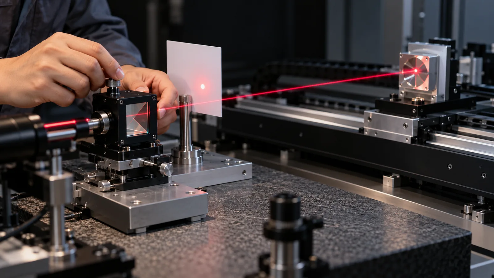
Deadpath is the distance between the interferometer's reference optic and the moving reflector at the start position. The laser wavelength is corrected for the measured environment along the entire path, but only the moving portion corresponds to stage displacement; the fixed portion still breathes with air refractive index and contributes an uncompensated error equal to the deadpath length multiplied by the fractional refractive-index change. In a room drifting by a degree, a 100-millimeter deadpath can inject error comparable to the stage tolerance under test.
Set the interferometer optics as close to the reflector's start position as the hardware allows, and record the residual gap. Where the gap cannot be eliminated, compensate analytically: with the deadpath known and the environment logged, the error term is calculable and subtractable. University metrology course notes treat deadpath as one of the four classical positional error sources, alongside wavelength compensation, cosine error and Abbe error, precisely because an otherwise excellent interferometer measurement can be dominated by it. Never leave deadpath implicit in a verification record.
Abbe error converts unwanted angular motion of the stage into apparent position error whenever the measurement line is offset from the axis the work actually follows. The contribution is the product of the angular error and the offset: classroom examples show that 10 arcseconds of pitch across a 100-millimeter offset already yields microns of error, and bench data from machine-tool verification shows positioning accuracy figures worsening severalfold as the mirror height moves away from the motion axis.
Two strategies cover the practical cases. When possible, place the interferometer measurement line through the working point—the tool center height, the wafer plane, or the encoder readhead line—so the offset approaches zero. When the offset is unavoidable, measure both the offset and the angular error profile along the stroke, then compensate the position error by the product of the two. The same logic applies in reverse to the stage itself: an encoder mounted close to the working axis shrinks the stage's own Abbe error, which is why readhead placement is a design decision, not an assembly detail.
An auditable verification captures the setup as carefully as the results. Log these items so a third party could reproduce the measurement and challenge the numbers.
The laser wavelength in air depends on refractive index, which tracks temperature, pressure and humidity. An environmental compensation unit sampling these quantities computes the correction from the Edlén relationship; the sensors must sit close to the beam path, because a temperature gradient between sensor and beam reproduces exactly the uncompensated error the unit exists to remove. Where the compensation data is suspect, manual wavelength calculation from independently measured conditions provides a cross-check.
The protocol itself should mirror how the stage will work. Warm the stage through representative duty cycles so structural thermal states match service, then measure bidirectional positioning error across the stroke at an agreed set of target points, with enough repeats to separate repeatability from drift. Add straightness and angular measurements when the acceptance criteria need them, using the appropriate optic sets. Verify the encoder's own error map against the interferometer result at the same time: discrepancies localize to either the scale, the interpolation or the installation rather than lurking in the total.
Acceptance is decidable only if the rule was fixed before measurement. State which results are acceptance criteria—positioning accuracy over stroke, bidirectional repeatability, reversal error—and which are informational, express the measurement uncertainty alongside each criterion, and define how an inconclusive result near the limit is handled. Retain raw position, angle and environment data so the commissioning record can be compared against production behavior years later.
This evidence discipline is the same one SENFU applies to optical encoder qualification and to lithography stage integration: the verification package—not a single accuracy number—is what makes the stage's specification defensible. For new stages, request the factory interferometer verification record with the same fields logged, then repeat a condensed version at incoming inspection to confirm nothing shifted in transport and installation.
CONCLUSION
Laser interferometry gives stage verification a traceable, nanometer-class reference, but the result inherits every weakness of the setup. Cosine error, deadpath, Abbe offset and uncompensated refractive index each exceed the tolerances being verified when left unmanaged, so the discipline of alignment, minimized deadpath, on-axis measurement and live environmental compensation is the substance of the method—not paperwork around it.
Fix the protocol and acceptance rule in advance, log the setup with the results, and compare the interferometer map against the encoder's own error report while both are on the bench. SENFU supplies optical encoder feedback for precision stages and can review the verification plan and acceptance evidence for your stage program.
EVIDENCE CHECKLIST
FAQ
Its wavelength is traceable to the SI definition of the meter, giving nanometer resolution and long-range accuracy no stage sensor can claim on its own. With air refractive index continuously measured, reported interferometer uncertainties for nanopositioning stage testing reach the half-nanometer class.
Deadpath is the fixed distance between the interferometer reference optic and the reflector at the start position. Changes in air refractive index over that uncompensated distance appear as position error equal to deadpath times the fractional index change. Mount the optics as close to the start position as possible and compensate any residual gap using logged environment data.
Cosine error grows with the square of the angle and with travel: a 0.01-degree misalignment produces roughly 50 micrometers of error per meter of motion. Align the beam to the motion axis at both ends of travel and confirm with a smooth trial motion before recording data.
Measure the offset and the stage's angular error profile along the stroke, then compensate each position by the product of the offset and the local angular error. Where the measurement line can be placed through the working axis—tool center height or wafer plane—do so, because the error term collapses toward zero.
As close to the laser beam path as practical. The compensation unit applies one refractive index correction along the path, so a temperature or pressure gradient between the sensor and the beam converts directly into wavelength error. Log the sensor locations as part of the verification record.
Yes. Measuring the encoder's position report against the interferometer during the same run localizes discrepancies to the scale, the interpolation electronics or the installation. It also establishes confidence in the encoder as the in-service reference between full verifications.
AUTHORITATIVE SOURCES
TECHNICAL REVIEW
Send the application, critical parameters and any drawing or process information available.
Discuss your application ↗