
Documentation matched to the purchase order
Verify part number, order code, resolution and interface variant, serial numbers, certificate of conformance and calibration certificate with its traceability chain and reference temperature.
TECHNOLOGY / ENCODER QUALITY
An incoming acceptance protocol catches shipping damage, wrong configurations and marginal signal quality before an encoder reaches a machine. This guide sets out the inspection sequence from packaging and documentation checks through Lissajous signal verification, count consistency, subdivision error sampling and record keeping, with the criteria that belong in each step.
Published

DIRECT ANSWER
Incoming acceptance is not a repeat of the factory test; it answers a different question. The factory test asks whether the encoder met its specification when it was built. Incoming acceptance asks whether this unit, with this serial number and this order code, arrived undamaged, correctly configured and still meeting that specification after shipping. The protocol runs in a fixed order so an expensive failure is never the first thing discovered: documentation and packaging first, then visual and electrical inspection, then signal quality, then counting behaviour, then a sampled accuracy or subdivision check, then records.
Four checks catch most real problems. The Lissajous figure of the sine and cosine channels shows amplitude, offset, quadrature and distortion in one display, and it is the fastest way to find a marginal readhead or a damaged cable. A count consistency test over a known distance proves the scale pitch, the interpolation setting and the interface configuration all match the order. A bidirectional reference-mark repeatability test reveals mechanical and signal problems that a single-direction move hides. And a document check against the purchase order catches wrong resolution codes and interface variants before they are built into a machine.
ENGINEERING CONTEXT
The cost of a missed incoming defect is asymmetric. An encoder that is wrong or marginal is discovered either in an hour on a bench or in a week inside a machine, where the same defect now has to be distinguished from cabling, grounding, controller configuration, mechanical alignment and process variation. Transport adds its own risk: shock and tilt events, condensation after a cold chain, contamination introduced during unpacking, and electrostatic damage from handling without a wrist strap. Most organisations have a receiving procedure for machined parts and none for encoders, which is why these failure modes are familiar to every integration engineer and surprising to every quality manager.
Discuss your requirement ↗CRITICAL REQUIREMENTS
Verify part number, order code, resolution and interface variant, serial numbers, certificate of conformance and calibration certificate with its traceability chain and reference temperature.
Record packaging condition, shock, tilt and moisture indicators and seal integrity, and photograph the outer packaging before opening so transport damage can be attributed.
Capture the Lissajous figure and signal amplitude across travel and at the extremes of the readhead gap, and keep the traces with the serial number record.
Run a known-distance count test and a bidirectional reference-mark repeatability test, at the maximum speed and acceleration the axis will use, before the unit is released to stores.
BUYER MATRIX
Give every shortlisted supplier the same process definition and request configuration-specific proof.
| Stage | What is measured | Instrument | Record produced |
|---|---|---|---|
| Documentation and packaging | Order code, resolution, interface variant, serial numbers, certificate scope, packaging and indicator condition | Purchase order, packing list, camera | Receiving record with photographs and any transport damage noted before unpacking |
| Visual and dimensional inspection | Scale and grating condition, coating, reference marks, readhead window, connector pins, cable jacket, mounting hole pattern, scale length | Stereo microscope or magnifier, scale or gauge | Inspection checklist with photographs of any mark or anomaly |
| Electrical and interface checks | Pinout continuity, supply voltage and current draw, interface option and frame or resolution format, status and error bits | Multimeter, pinout drawing, controller or interface card | Electrical check record including the configuration revision read from the device |
| Signal quality and Lissajous | Sine and cosine amplitude, DC offset, quadrature deviation, harmonic distortion, margin across travel and gap | Oscilloscope in X-Y mode, or controller diagnostic display | Saved Lissajous traces and amplitude figures at defined travel positions and gap settings |
| Count consistency | Counts returned over a known displacement, phase relationship of the quadrature channels, behaviour at maximum speed and acceleration | Gauge block, step gauge or laser interferometer, counter or controller | Count error per unit length and a pass or fail against the interpolation setting on the order |
| Reference-mark repeatability | Position returned when approaching the reference mark repeatedly from both directions | Controller with a bidirectional approach routine | Repeatability figure from a defined number of approaches in each direction |
| Subdivision error sample | Short-period error repeating once per signal period, measured against a displacement reference at constant low speed | Laser interferometer or high-resolution reference system | Subdivision error amplitude in nanometres with speed, temperature and method stated |
| Records and disposition | Traceability of the result to the unit, uncertainty of the reference, decision and storage condition | Quality system, certificate of conformance | Serial-numbered acceptance report, non-conformance record if failed, and defined storage or release |
A factory calibration certificate describes a unit at a moment in the past, under conditions the supplier controlled. Incoming acceptance describes the same unit now, after shipping, handling and storage, in the configuration the buyer will install. The two are not redundant: the certificate supports traceability, while the incoming test supports the decision to build this unit into a machine. Skipping the second turns every later integration problem into a forensic exercise, because the state of the encoder on arrival was never recorded.
The protocol is ordered deliberately, and the order matters more than any individual test. Documentation and packaging come first because they are cheap and often end the inspection early: a wrong resolution code or a broken seal does not need a metrology laboratory. Electrical checks come before motion, because applying power to a mis-wired connector is the fastest way to turn a receiving error into a scrap unit. Only then does the expensive part begin, on a unit known to be the right one and known to be powered correctly.
Reconcile the packing list against the purchase order before anything is unpacked: part number and revision, order code, resolution and interface variant, cable length and connector type, scale length, and the serial numbers of readhead and scale. Confirm the certificate of conformance matches those serial numbers, and check that any calibration certificate states what was measured, over what travel, at what reference temperature, against what reference instrument and with what traceability. A certificate quoting an accuracy figure without a method or a temperature cannot be used as an acceptance criterion later.
Then inspect the packaging rather than the product. Photograph the outer carton, record any shock, tilt or humidity indicator that has tripped, note whether seals and desiccant are intact, and check whether vacuum or cleanroom units arrived in the specified sealed condition. Allow the unit to reach the temperature of the inspection area and record both, because a scale measured while still warming is being measured for nothing. Quarantine the unit until the documentation check passes, so nothing under investigation reaches a machine.
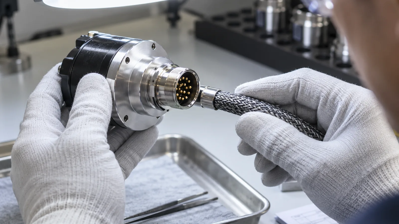
Handle scale and readhead as optical parts, on a clean bench, with gloves and a wrist strap. On the scale, look along the grating under a magnifier for scratches, digs, clouding, coating damage, adhesive residue and fingerprints, and check the reference mark. On the readhead, inspect the optical window, mounting faces, connector pins, cable jacket and strain relief. Check the mounting hole pattern and the scale length against the installation drawing. Photograph any anomaly before touching the part again, because contamination and coating damage can be caused by handling as well as by manufacture.
Never apply power on trust. Verify continuity and pinout against the encoder drawing, confirm no signal conductor is shorted to shield or supply, and check supply voltage and current draw on first power-up against the documented figure. For an absolute encoder, read back the configured interface, resolution format and frame length and confirm they match the order code; a correct part number with a wrong factory configuration is one of the most avoidable receiving errors. For serial interfaces, read the status bits before commanding motion and record the configuration revision.
Plot the sine channel against the cosine channel in X-Y mode and read the figure. A healthy signal is a clean, centred circle: the radius is the amplitude, the centre is the DC offset, the roundness is the quadrature and harmonic quality. An offset displaces the circle, an amplitude mismatch between channels turns it into an ellipse aligned with an axis, a phase error away from quadrature rotates that ellipse onto the diagonals, and distortion bends the outline away from circular. Each defect becomes subdivision error as soon as the interpolator divides the period.
Do not check it once. Capture the figure at several positions along the travel and at both extremes of the permitted readhead gap, because a scale with a local contamination patch or a slightly bowed mounting surface gives a good figure at mid-travel and a poor one at the ends. Record amplitude against the documented window rather than against a memory of what it usually is. An amplitude inside the window with clean geometry is the evidence that the optical, mechanical and electrical parts of the assembly survived transport.
Drive the axis over a known distance and compare the counts with the distance divided by the configured resolution; a gauge block or step gauge is enough for a coarse check, and a laser interferometer is the right reference where the result must be defensible. This confirms three things at once: the scale pitch matches the drawing, the interpolation setting matches the order, and the counting chain loses nothing. Watch the quadrature phase relationship through reversals, then repeat the test at maximum speed and acceleration, because a unit that counts correctly at crawl speed can still lose counts at speed.
Then sample subdivision error. Run at constant low speed against a displacement reference and look for a component repeating once per signal period; that component is the interpolation error, and it is the term most sensitive to signal quality, gap stability and contamination. State speed, direction, temperature, gap, instrument and uncertainty with the result, and compare the amplitude in nanometres against a criterion set before the order. Finally, approach the reference mark a defined number of times from each direction and record the spread of the returned positions; a single-direction result hides reversal error and signal asymmetry.
The output is a serial-numbered acceptance report that someone else can read a year later. It should list the purchase order and order code, the serial numbers, the documents received and their scope, the environmental conditions, every measured result with the instrument and its traceability, and a clear pass or fail against criteria written before the unit arrived. Criteria written after seeing the data are not criteria, they are a justification. Where a criterion comes from a datasheet figure, quote the datasheet and its conditions next to it.
Define the failure path as well. A failed unit goes to quarantine with a non-conformance record stating the observed result, the criterion and the disposition request, and it is returned with the packaging photographs and the serial number rather than alone. For batch receipts, set a sampling level in advance and tighten it after any failure, because one bad unit in a lot is a statement about the rest of the lot. Over time the accumulated reports become the evidence that a supplier is stable, which is worth more than any single certificate.
CONCLUSION
An incoming acceptance protocol turns encoder receiving from a formality into a control. The sequence is stable because the logic is stable: prove the unit is the right one and undamaged before spending metrology time on it, prove it is wired and configured correctly before powering motion, prove the signal is clean before trusting any position result, and record every result against a criterion written before the box was opened. The cost is an hour per unit at the bench; the saving is the week a marginal encoder would otherwise spend inside a machine, suspected of nothing in particular.
EVIDENCE CHECKLIST
FAQ
Yes, because the two answer different questions. The certificate describes the unit at the factory under the supplier's conditions. Incoming acceptance describes this unit, in this configuration, after shipping and handling. Only the second supports the decision to build it into a machine.
It plots the sine channel against the cosine channel. A healthy signal is a clean centred circle: offset displaces it, amplitude mismatch makes it elliptical, a phase error away from quadrature rotates the ellipse, and distortion makes the outline non-circular. Each defect becomes subdivision error in the interpolator.
Move the axis over a known distance using a gauge block, step gauge or laser interferometer and compare the returned counts against distance divided by the configured resolution. Repeat it at the maximum speed and acceleration the axis will use, because marginal receivers can count correctly slowly and lose counts at speed.
Usually not. A full-travel map is a factory or calibration activity. Incoming inspection should sample subdivision error at constant low speed against a reference, with conditions stated, and escalate to a full map when the application justifies it or a sample result is near the limit.
Purchase order and order code, serial numbers, documents received and their scope, environmental conditions, every measured result with the instrument and its traceability, and a pass or fail against criteria written before arrival. Store it by serial number so the history follows the unit.
AUTHORITATIVE SOURCES
TECHNICAL REVIEW
Send the application, critical parameters and any drawing or process information available.
Discuss your application ↗