
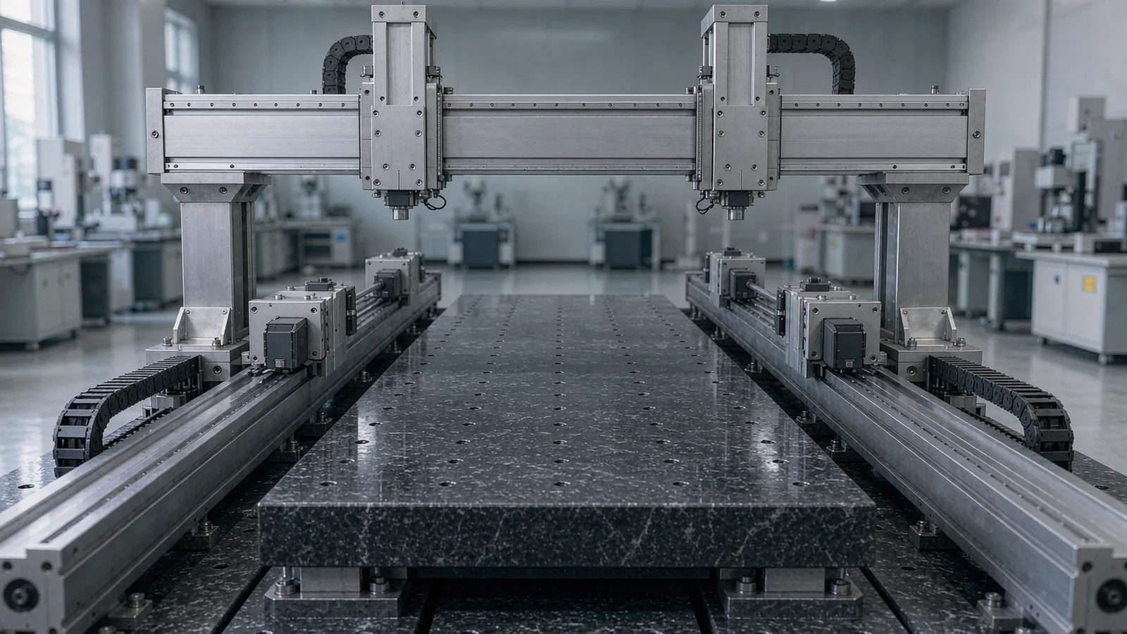
Dual full closed-loop feedback
One linear scale and readhead per side, referenced to the machine table so that yaw and differential position are measured directly at the point of use.
TECHNOLOGY / GANTRY MOTION CONTROL
How to design, calibrate and verify synchronized dual-encoder feedback on gantry stages: dual readheads, cross-coupling error, control architecture and acceptance testing.
Published
DIRECT ANSWER
A dual-drive gantry needs one closed position loop per side, measured at the moving table with two linear readheads, and a controller that treats the pair as one synchronized axis rather than two independent servos. Synchronization quality is set by encoder bandwidth, cross-coupling compensation, mechanical stiffness and the calibration of both measurement lines. Verify yaw, tracking error and differential position with one acceptance method on every machine.
ENGINEERING CONTEXT
On a gantry stage, the two drive and measurement chains share one mechanical structure but see different loads, cable paths, thermal conditions and servo tuning. If each side is commissioned independently, the controller can fight itself: small phase or gain differences become yaw motion, edge tilt and long settling times. The engineering task is to make the two feedback chains electrically, mechanically and dynamically equivalent, then calibrate and verify them as a single metrology system.
Discuss your requirement ↗CRITICAL REQUIREMENTS
One linear scale and readhead per side, referenced to the machine table so that yaw and differential position are measured directly at the point of use.
A master-slave or dual-loop control scheme with matched gain, bandwidth, interpolation settings and update rates on both channels.
Defined methods for differential error, cross-coupling compensation, yaw and dynamic tracking error, applied identically at commissioning and during service.
BUYER MATRIX
Give every shortlisted supplier the same process definition and request configuration-specific proof.
| Design decision | Single encoder on one side | Dual readheads, full closed loop |
|---|---|---|
| Measured quantity | One-side position only; opposite-side motion is inferred from mechanics | Both side positions; yaw and differential offset measured directly |
| Cross-coupling visibility | Hidden in overall positioning error; hard to separate from drive error | Explicit in the difference signal; can be compensated per axis pair |
| Thermal sensitivity | Asymmetric expansion between measured and unmeasured side goes uncorrected | Symmetric mounting allows matched expansion behavior and simpler compensation |
| Controller complexity | Lower cost, but relies on mechanical coupling to keep the second side aligned | Requires synchronized dual channels, matched interpolation and more commissioning effort |
| Failure behavior | A drifting mechanical coupling changes geometry without a position alarm | Differential alarm limits can detect binding, lost motion or side divergence |
A gantry stage drives the same rigid crossbar from two parallel linear axes. When only one side carries an encoder, the controller knows the position of that one carriage and assumes the other follows through mechanical coupling. Any difference in friction, backlash, stiffness or thermal growth between the sides appears as twist instead of position error, and the control loop cannot see it. The result is a stage that repeats at one corner but drifts or oscillates at the other.
The standard correction is to measure both sides. With a linear scale and readhead on each rail, the controller receives two independent position signals and can drive the motors against their difference as well as their average. This converts yaw from an invisible mechanical effect into a controlled variable. The same measurement redundancy also creates a diagnostic channel: when the two readings diverge beyond a defined limit, the machine can stop instead of dragging a skewed crossbar through a process.
Measurement at the table, not at the motor shaft, is what makes this work. Rotating motor encoders observe ball-screw rotation, so pitch error, screw compliance and coupling slip all sit inside the loop. Linear scales close the loop around the whole mechanical chain, which is why full closed-loop feedback is the baseline for synchronization on precision gantries.
Cross-coupling error is the position error that motion on one axis induces in another. On a gantry, the two longitudinal drives are coupled through the crossbar, so acceleration on one side loads the opposite drive, flexes the bridge and deflects the vertical structures that carry the payload. In a two-axis gantry with X drives and a Y bridge, X motion can shift Y indication and vice versa, and the coupling grows with acceleration and with the distance between the measurement line and the drive line.
The coupling is not random. It has a repeatable dynamic component proportional to acceleration and a slower component from thermal and structural drift. Dynamic coupling is addressed in the controller: cross-coupling feedforward, matched servo gains and synchronized trajectory generation for both drives reduce the differential command error. Structural coupling is addressed mechanically: stiffening the bridge, moving the measurement lines closer to the drive lines and reducing the Abbe offset between scale and workplane.
Do not expect compensation to replace measurement quality. Cross-coupling feedforward can only cancel error that both encoder channels actually observe. If one side has no encoder, poor signal bandwidth or an unmatched interpolation filter delay, the compensation acts on stale or asymmetric data and can amplify yaw at speed. Match the two feedback channels first, then tune the compensation.
Three architectural decisions define a synchronized gantry. First, control topology: a master-slave scheme commands one side and derives the other from the difference signal, while a cross-coupled scheme servo-controls the average position and the difference position as two separate loops. Cross-coupled control is generally preferred for precision gantries because the difference loop can be tuned independently of the path loop.
Second, channel equivalence: both readheads, scales, cables and interpolators should have matched resolution, filter settings and update rates. A mismatch of even a few sampling periods between channels appears as a velocity-dependent yaw error that looks like a mechanical fault. Record the interpolation settings of both channels in the machine file and lock them through configuration control.
Third, alarm strategy: define differential position limits, rate-of-change limits on the difference signal and a recovery procedure for synchronization faults. Commissioning data shows typical differential ripple; set alarm thresholds above that ripple but far below values that indicate binding, scale contamination or a readhead fault. For long-travel or high-speed gantries, evaluate output frequency at maximum velocity on both channels, as documented in the scale-pitch and speed selection guide, so neither interface becomes the bandwidth bottleneck.
Calibration of a dual-drive gantry has two layers. The first is per-axis: measure the linear error of each scale over full travel with a reference interferometer or a calibrated comparator, and load the per-axis compensation table into the controller. The second is paired: measure the difference between the two channels at fixed points along travel, with and without payload, and record the yaw map of the crossbar.
The paired measurement exposes installation contributions that per-axis calibration hides: a slightly rotated scale on one side, a residual Abbe offset or an asymmetric thermal gradient. Many teams run the paired measurement at cold start and again after a defined warm-up cycle, because the difference between the two states is the thermal signature that the differential alarm thresholds must tolerate.
After compensation, verify with dynamic tests: bidirectional positioning per travel position, small-step reversal measurements and a full-speed contour run while logging the differential signal. A stage that passes static calibration but shows differential spikes during acceleration still has coupling or channel-mismatch problems. Log raw differential data at commissioning and archive it; it becomes the baseline for future service comparisons and for validating any later change to scales, cables or control firmware.
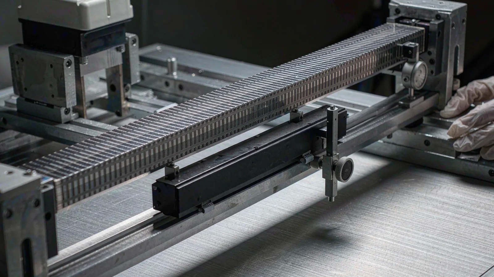
An acceptance plan for a synchronized gantry should state four things before the first measurement: the positioning and repeatability limits for each side, the allowable differential position across travel and during motion, the yaw limit at the workplane, and the measurement method and uncertainty used to judge each value. Machine-tool positioning tests of the kind described in ISO 230-2 give a structured starting point, but the differential and yaw criteria are machine-specific and must come from the process error budget.
Long-term stability depends less on the initial tuning than on what changes afterward. Scale mounting adhesive creep, cable fatigue, readhead bracket loosening and thermal gradient shifts all show up in the differential signal before they appear as process defects. Trending the differential error at a fixed reference point during regular warm-up cycles gives an early warning at essentially zero cost.
Finally, treat synchronization as a configuration, not just a measurement. Any replacement of a scale, readhead, cable or interpolation module on one side breaks channel equivalence until the pair is re-verified. Writing that rule into the maintenance plan is the cheapest synchronization insurance available.
CONCLUSION
Dual-drive gantry synchronization succeeds when both sides are measured at the table, the two feedback channels are electrically and dynamically equivalent, cross-coupling is compensated from paired calibration data, and the differential signal becomes a permanent health monitor. None of these steps is exotic; the discipline is treating the two encoders as one metrology system from design through service.
For a SENFU review, provide the gantry travel and speed profile, payload, controller and interface type, differential and yaw targets, and the installation envelope on both rails. SENFU can map those inputs to source-backed encoder configurations, flag channel-matching requirements and prepare the questions to close before commissioning.
SOLUTION ROUTES
EVIDENCE CHECKLIST
FAQ
Mechanical coupling transmits position but does not measure it. Friction, stiffness and thermal differences between the sides produce yaw that a single encoder cannot observe. Two linear readheads at the table make the differential position a controlled, alarmed variable and close the loop around the full mechanical chain.
It is the error induced in one axis by motion of another through the shared structure. Acceleration on one drive loads the opposite drive and flexes the bridge, shifting the crossbar. It is reduced by matched servo tuning, cross-coupling feedforward, structural stiffness and measurement lines placed close to the drive lines.
Cross-coupled control, which servo-controls average position and the difference between the two encoders as separate loops, is generally preferred for precision stages because the difference loop can be tuned and limited independently. Master-slave remains acceptable for lower-load, lower-precision applications.
There is no universal period. Recalibrate per-axis and paired error after any scale, readhead, cable or interpolation change on one side, after mechanical service on the bridge, and when trending of the differential signal at a fixed reference point shows drift beyond defined limits.
Partly. A step change or noise pattern in one channel suggests a readhead, cable or interpolation issue, while slow thermal-rate drift or divergence that correlates with acceleration suggests mechanical coupling, binding or compensation error. Logging raw differential data makes the distinction diagnosable.
AUTHORITATIVE SOURCES
TECHNICAL REVIEW
Send the application, critical parameters and any drawing or process information available.
Discuss your application ↗