
Geometric budget
Define straightness, flatness, pitch, roll and yaw allowances over full travel, and split them between the stage structure, the scale reference and the mapping.
TECHNOLOGY / AIR-BEARING STAGE METROLOGY
Select encoders for air-bearing stages by defining out-of-plane motion, flatness and straightness limits, scale mounting strategy and a signal budget that survives the air film.
Published
DIRECT ANSWER
An air-bearing stage removes sliding friction, so the remaining position errors are dominated by the geometry the encoder actually sees: scale straightness and flatness along the travel, out-of-plane motion of the carriage as it floats, and the readhead-to-scale gap stability that the air film and structural design allow. Encoder selection should therefore start with an out-of-plane and straightness budget for the stage, not with a resolution number from a catalogue.
The practical selection sequence is: define the allowable mapping error over the full travel, choose a scale accuracy class and mounting method whose reference surface beats that budget, specify the readhead gap window against the measured carriage float, and then require a mapped straightness and flatness report plus a gap-stability demonstration at acceptance. Averaging effects and multi-readhead schemes can reduce short-period error, but only after the geometric budget is closed.
ENGINEERING CONTEXT
Air-bearing stages can deliver sub-micron straightness and near-frictionless motion, which is exactly why a mediocre encoder choice becomes visible. The scale rides on the same structure that floats on air, the gap between readhead and scale breathes with the film, and contact-based datum strategies no longer apply. Buyers must convert a smooth-motion impression into a mapped geometric and signal budget before the encoder can be qualified.
Discuss your requirement ↗CRITICAL REQUIREMENTS
Define straightness, flatness, pitch, roll and yaw allowances over full travel, and split them between the stage structure, the scale reference and the mapping.
Characterize carriage float, gap variation and attitude change with load and position, and confirm the readhead tolerance window against those numbers.
Require signal margin over the full travel, a mapped accuracy report against a traceable reference, and the interpolation error contribution stated separately.
BUYER MATRIX
Give every shortlisted supplier the same process definition and request configuration-specific proof.
| Decision | Evidence to obtain | Risk if left open |
|---|---|---|
| Scale accuracy class | Mapped accuracy report over full travel with traceable reference and stated mapping interval | Straightness error of the scale appears as position error that no interpolation can remove |
| Scale mounting | Mounting datum design, adhesive or clamp procedure, substrate material and flatness verification after mounting | Mounted scale straightness differs from the catalogue value |
| Readhead gap window | Nominal gap, tolerance range, and measured carriage float and attitude across travel and load cases | Signal loss or cyclic error when the film thickness changes with position |
| Averaging and readhead count | Readhead spacing rationale, expected short-period error reduction and combined signal handling | Two readheads are installed without a combined-error analysis and reduce nothing |
| Signal budget | Signal amplitude, DC balance and margin over full travel including worst-case gap | Interpolation error grows near travel ends where the signal degrades first |
| Acceptance mapping | Straightness and flatness map plus position error map against a laser or equivalent traceable reference | Stage passes a short-travel check and fails the full-travel specification |
On a contact-guided stage, the guide decides where the carriage is and the encoder reports it. On an air-bearing stage the carriage floats, so vertical and angular motion are properties of the film, the load distribution and the opposing surfaces. Before comparing encoders, write down how much out-of-plane motion the application tolerates at the point of interest, and how much of that motion the encoder should see versus reject.
Then split the in-plane position budget the same way. Full-travel straightness of the scale reference, pitch and yaw of the carriage, and the interpolation error of the readhead electronics all contribute. A catalogue resolution of nanometers is meaningless if the mounted scale straightness consumes microns of the budget over travel. The encoder conversation should therefore begin with the geometric budget table, and the supplier should confirm which part of that table their accuracy class and mapping service covers.
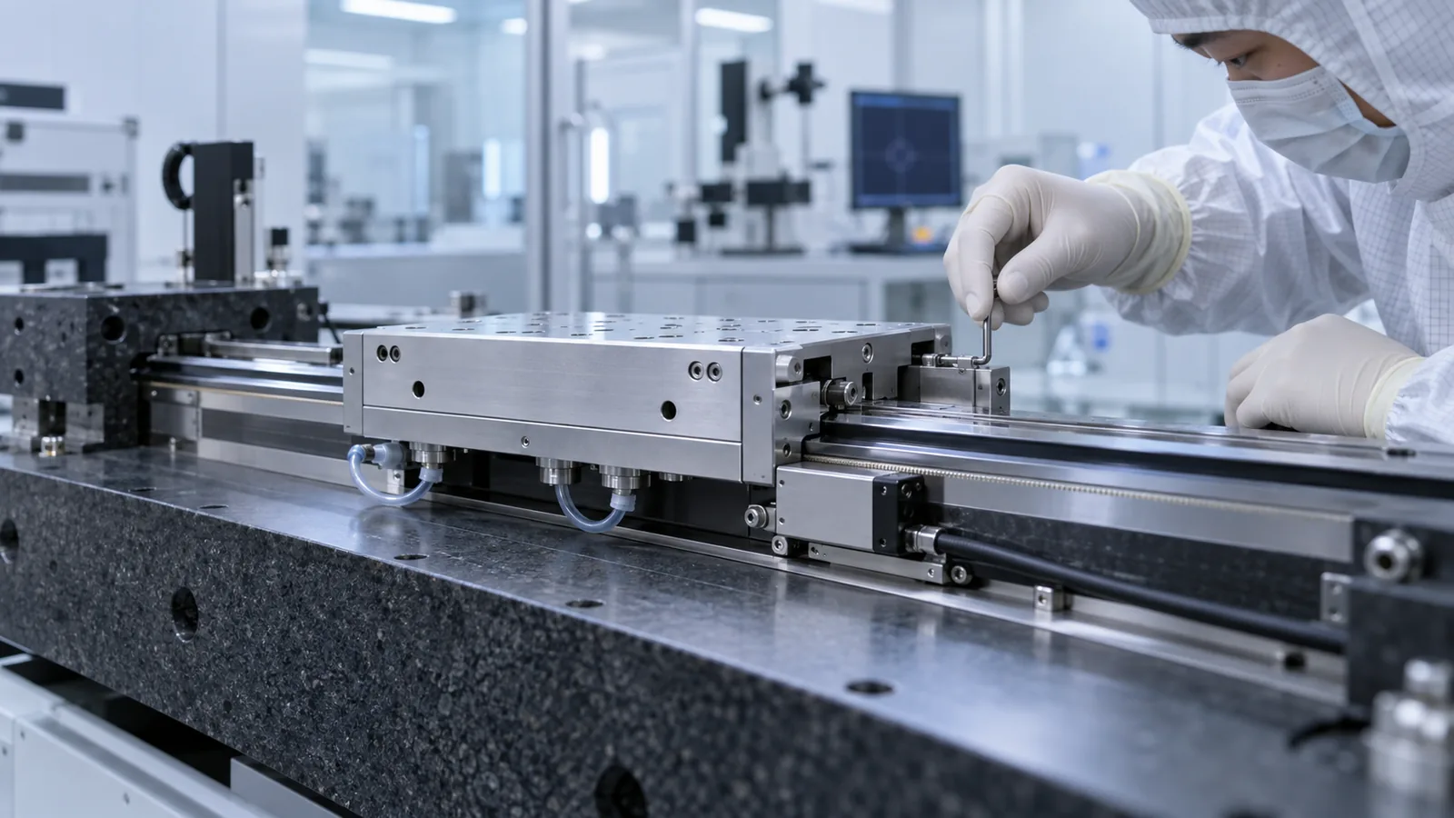
Air-bearing stages typically carry scales on granite, ceramic or ultra-stable alloy structures. The mounting method transfers the substrate's flatness into the scale's effective reference: an adhesive bond follows the local substrate shape, a clamped scale follows its own straightness only where the clamp pattern allows. Ask for the recommended mounting pattern, the substrate flatness requirement under the scale line, and the verification method after mounting.
Thermal behavior joins the geometry here. The same reasoning as any precision metrology loop applies: decide whether position should follow the scale, the structure or the workpiece, and choose materials and datum strategy accordingly. Related guidance is in the linear encoder thermal error budget article, and the installation tolerances involved are treated in detail in the readhead gap and installation tolerance guide.
A readhead measures a gap. On an air bearing, that gap breathes: film thickness varies with load, supply pressure, travel position and temperature, and the carriage attitude changes as the film redistributes. The encoder selection must therefore include a gap-stability requirement: measure float and attitude change across travel and load cases, and confirm that the worst case still sits inside the readhead's specified gap window with signal margin to spare.
Signal quality is the acceptance evidence for this. Ask for amplitude and DC balance records along the full travel, not just at a friendly mid-travel position. Where the margin is thin, either the mechanical design or the encoder choice must change before the stage is built, not after it fails a map at the ends of travel.
Multiple readheads and wide averaging windows reduce short-period and interpolation-related error contributions, and they can average out some local scale imperfections. They cannot remove the long-period geometric error created by scale straightness or by the stage structure, and they cannot compensate an out-of-plane motion that takes the readhead outside its linear gap range.
The correct order is therefore: close the geometric budget first, then apply averaging to the residual short-period terms, and verify the combination with a full-travel map. Buying a second readhead to hide a straightness problem usually produces an expensive stage that still fails its map.
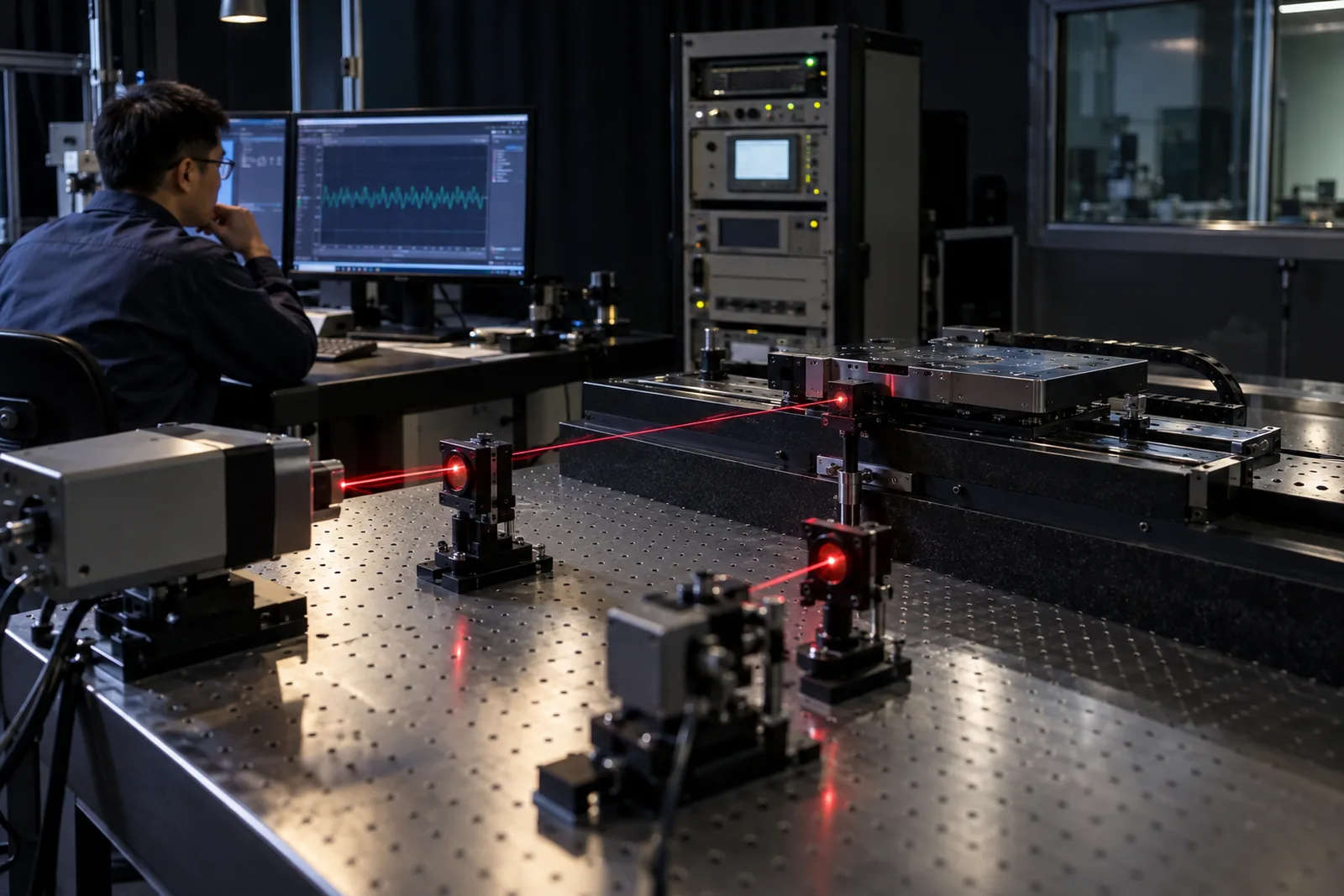
The acceptance package should contain: a full-travel straightness and flatness map of the mounted scale against a traceable reference; a position error map with the mapping interval stated; the interpolation error contribution measured separately; signal amplitude and balance records across travel; and a gap-stability record across the load and position cases defined in the budget.
Suppliers who manufacture the complete feedback chain can provide these as one coherent set. SENFU's optical encoder families are specified with exactly this division between catalogue performance and installed evidence, and the applications team can review the budget table with the buyer's mechanical drawing before the stage is built.
CONCLUSION
Air-bearing stages expose the encoder to its hardest test: no friction to mask geometry, and a measuring gap that lives on air. Write the out-of-plane and straightness budget first, choose the scale class and mounting that satisfy it, hold the readhead inside its gap window with measured margin, and accept the installation on a full-travel map with separate interpolation evidence. Stages selected this way deliver the smoothness their air film promises instead of a resolution figure the geometry never supported.
EVIDENCE CHECKLIST
FAQ
Catalogue accuracy describes the scale under reference conditions and mounting. After mounting on the stage substrate, effective straightness reflects the substrate and the mounting method, and out-of-plane motion changes the readhead gap. The installed result must be mapped; the catalogue value is only an input to the budget.
It depends on the readhead design and its stated gap window. The correct procedure is to measure carriage float and attitude across travel and load cases, then confirm that the worst-case combination stays inside the window with signal margin. If it does not, change the mechanical design or the encoder, not the acceptance criterion.
No. Dual readheads and averaging reduce short-period and interpolation-related error, but they cannot correct long-period geometric error from scale straightness or structure. Apply averaging after the geometric budget is closed, and verify the combination with a full-travel map.
A full-travel straightness and flatness map against a traceable reference, a position error map with mapping interval, separately stated interpolation error, signal amplitude and balance across travel, and a gap-stability record across the defined load cases.
AUTHORITATIVE SOURCES
TECHNICAL REVIEW
Send the application, critical parameters and any drawing or process information available.
Discuss your application ↗