
Measure at the receiving end
Probe at the controller or drive input with the production cable installed. Signal measured at the readhead on a short test lead hides cable, termination and grounding effects that are frequently the real cause.
TECHNOLOGY / ENCODER SIGNAL DIAGNOSTICS
A practical diagnostic guide to optical linear encoder output quality: what a clean analog sine or incremental square wave should look like, how amplitude loss, phase error, DC offset and edge jitter manifest on a scope and in the servo, the measurement sequence that separates optical, mechanical and electrical causes, and the acceptance limits worth writing into a commissioning record.
Published
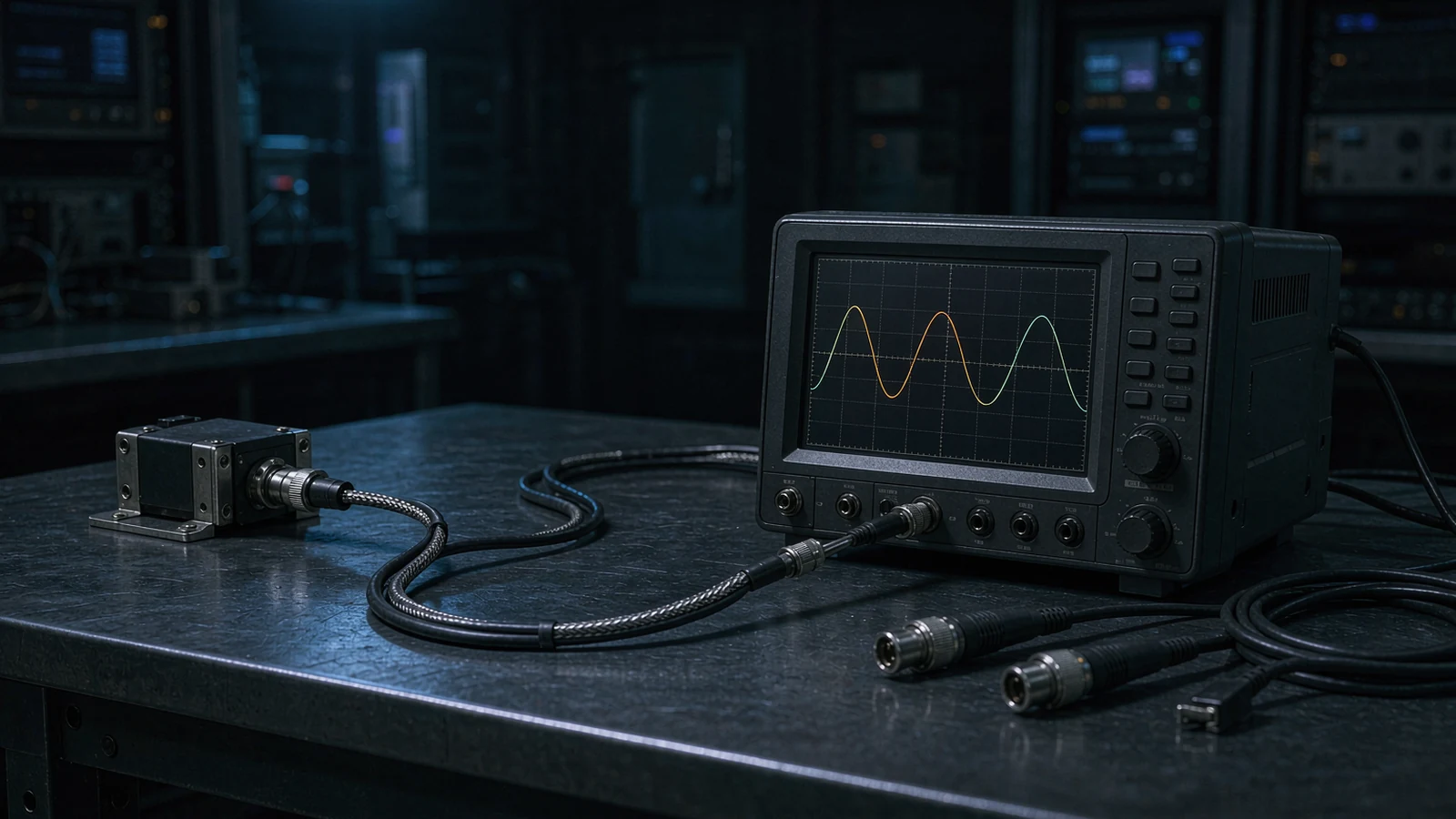
DIRECT ANSWER
Encoder signal problems are diagnosed by separating four independent defects: amplitude, phase, offset and noise. Measure each one separately at the controller end of the installed cable, not at the readhead on a bench, and always under the duty cycle that produces the fault.
A working diagnostic order is: confirm supply and reference integrity; measure A and B amplitude and their ratio at constant speed; measure the A-to-B phase relationship; measure the DC offset of each channel against its own midpoint; then measure edge jitter and noise on the digital or interpolated output. Amplitude loss points to gap, contamination or supply; phase error points to readhead alignment or optics; offset points to termination, ground or a damaged channel; jitter that scales with speed points to noise or bandwidth, while jitter concentrated at particular positions points to scale contamination or mechanical resonance.
ENGINEERING CONTEXT
An optical encoder produces a measurement only as good as the analog signal behind it, and almost every real-world fault degrades that signal before it degrades the position reading. By the time a machine reports a position error, the underlying cause has usually been present for weeks as reduced signal margin. The difficulty is that the symptoms of very different root causes look identical from the controller: intermittent count errors, jitter at particular speeds, failure to home, or drift after warm-up. Teams replace readheads and controllers because those are easy to swap, while the actual cause is a contaminated scale, a readhead gap at the edge of tolerance, a missing termination resistor, or a bracket resonance that modulates the gap. A structured signal measurement finds these in minutes and prevents the parts-swapping loop entirely.
Discuss your requirement ↗CRITICAL REQUIREMENTS
Probe at the controller or drive input with the production cable installed. Signal measured at the readhead on a short test lead hides cable, termination and grounding effects that are frequently the real cause.
Treat amplitude, phase, offset and noise as independent quantities and measure each explicitly. A single composite check such as 'does it count' cannot distinguish them and therefore cannot point to a cause.
Reproduce the speed, acceleration, temperature and machine state that produces the fault. Static bench checks pass on encoders that fail in production because the excitation is missing.
Capture amplitude, offset, phase and jitter at commissioning with the supplier's specified limits, then re-measure at planned intervals so that gradual degradation is visible before it becomes a fault.
BUYER MATRIX
Give every shortlisted supplier the same process definition and request configuration-specific proof.
| Symptom | Measurement that isolates it | Likely root cause | First corrective action |
|---|---|---|---|
| A and B amplitude both low, ratio near unity | Peak-to-peak amplitude of each sine channel measured at constant speed and compared with the supplier's specified window | Readhead gap at the limit of tolerance, contamination film on the scale, aged emitter, or supply voltage out of specification | Verify supply at the readhead under load, then check gap and clean the scale using an approved method |
| One channel lower than the other, amplitude ratio off | Ratio of A amplitude to B amplitude; a healthy pair is close to unity with a small stated tolerance | Readhead yaw or tilt relative to the scale, localised scale damage, partial obscuration, or an unbalanced load on one channel | Re-check readhead alignment against the installation drawing, inspect the scale length for local defects |
| Phase relationship deviates from quadrature | Time between corresponding A and B zero crossings expressed as a fraction of one signal period; ideally one quarter period | Readhead rotation relative to the scale, optical path asymmetry, or interpolation setup mismatch for the installed pitch | Correct readhead angular alignment and confirm the interpolation configuration matches the scale pitch |
| Sine channels shifted away from their midpoint | DC offset of each channel measured against its own midpoint, and differential offset between the A+ and A- pair | Incorrect or missing differential termination, ground potential difference between machine and controller, shield connection error, or a damaged channel | Check termination resistor values at the receiver, then measure ground potential difference and correct shield and cable routing |
| Jitter that increases with speed | Edge timing variation on the digital output, or position noise from the controller, sampled at several constant speeds | Noise coupled into the signal path, insufficient bandwidth or slew rate, cable length beyond specification for that output frequency | Review cable routing, shielding and grounding, then verify output frequency against the controller input limit |
| Jitter concentrated at particular positions or machine states | Position-resolved noise recorded while traversing the full travel, correlated with machine operation | Localised scale contamination or damage, mechanical resonance modulating the gap, or coolant and mist on the scale at those locations | Inspect and clean the affected scale region, and measure the acceleration spectrum at the readhead while the symptom is present |
| Intermittent errors only after warm-up or after hours of running | Amplitude and error counters logged over a full thermal cycle | Thermal drift of the gap through differential expansion, condensation on optics, or a marginal supply that sags with temperature | Log amplitude over a full cycle and compare against the commissioning baseline; review thermal and sealing provisions |
An optical linear encoder generates periodic signals as the readhead moves across the scale pattern. In analog form these are two sinusoidal channels in quadrature: identical amplitude, one quarter of a period apart in phase, centred on a common reference level. In digital or interpolated form the same information appears as square waves or a serial position word, but the quality of the underlying analog pair still determines the result. Interpolation divides each period into smaller increments and can only do so accurately if the pair is clean, balanced and correctly phased.
Four quantities therefore describe signal health completely. Amplitude is the peak-to-peak value of each channel and should sit inside the window the supplier specifies; too little amplitude leaves no margin for contamination or ageing, and too much can indicate an incorrect supply or a gain setting. Amplitude balance is the ratio between the two channels and is sensitive to readhead alignment. Phase is the quadrature relationship and is the classic signature of alignment and optical asymmetry. Offset is the DC position of each channel relative to its midpoint, and in a differential pair it is the symmetry between the true and complement signals. Noise and jitter describe how stable the transition timing is, and they set the practical floor on position repeatability.
It is worth stating what these are not: amplitude is not accuracy, and a clean signal does not guarantee an accurate axis. Mounting, scale error, thermal expansion and Abbe offsets still determine the system result. Signal quality is the foundation: if it is poor, nothing downstream can recover the measurement.
Amplitude is the most informative single number because it responds to both optical and mechanical conditions. The dominant mechanical cause is readhead gap: amplitude falls as the gap moves away from its optimum, and the gap changes with installation tolerance, thermal expansion and structural deflection, so amplitude can be correct at commissioning and degraded months later. The dominant optical cause is a film on the scale: coolant residue, fingerprints, condensed moisture or dust, which scatters light and reduces contrast gradually.
Electrical causes are just as common and are overlooked because the encoder still works. Supply voltage at the readhead is not the supply voltage at the power supply: cable resistance, connector contact resistance and shared loads all drop volts along the run, and a readhead below its specified range produces reduced amplitude that looks identical to contamination. Measure at the readhead under load and size the cable accordingly.
Imbalance between the two channels narrows the cause list. Because both channels share the optical path and the electronics, a large amplitude difference usually indicates geometry rather than gain: the readhead is yawed or tilted, or localised damage affects one sensing region. Re-check alignment against the installation drawing before considering an electronic cause, and inspect the scale over the full travel.
Quadrature error is measured by comparing the time between corresponding zero crossings of the two channels against one signal period. In an ideal pair that interval is one quarter of the period; a few degrees of deviation is normal in a real installation, but larger deviation produces interpolation error that varies within each period. Because it repeats with the scale pitch, users describe it as an axis that is accurate at some positions and not others. The primary cause is angular misalignment of the readhead, so the first action is mechanical.
DC offset shifts the signals away from their midpoint. Small offsets degrade interpolation because the algorithm assumes a centred sine and cosine; large offsets make the digital conversion behave asymmetrically within a period. In differential signalling, offset should first be checked as symmetry between the true and complement lines. Asymmetry usually means a termination problem: differential receivers require the specified termination at the receiving end, and a missing or wrong-value resistor produces exactly this signature. Ground potential differences between the machine structure and the controller cabinet produce the same effect, as does a shield carrying current through the signal reference.
The distinction that matters in practice is where the offset appears. Offset present at the readhead on a short test lead but not through the production cable indicates a cable or receiver-side problem. Offset present only with the machine running and absent with the controller idle indicates coupling or grounding. Offset that appears after a cable was replaced or re-terminated points at the termination itself. Each of these has a different fix, and measuring at both ends of the installed cable is what separates them.
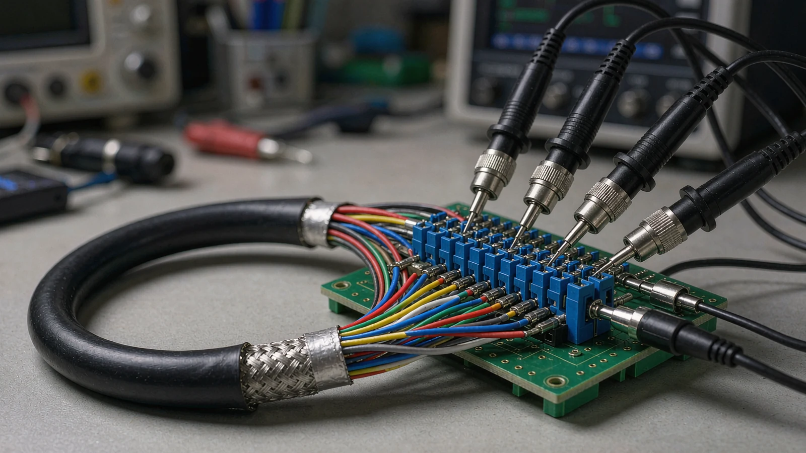
Run this sequence with the production cable installed, probing at the controller input, and record every value:
Jitter describes variation in the timing of output transitions, which translates directly into position noise. Its diagnostic value lies in what it correlates with. Jitter that scales smoothly with speed points to noise coupling or bandwidth, as edge rates approach what the receiver or cable can support. Jitter at discrete speeds usually indicates a mechanical resonance modulating the gap or a speed-dependent interference source such as a drive carrier frequency. Jitter concentrated at particular positions points to localised scale contamination.
Edge quality is worth inspecting directly. Slow or rounded edges, ringing or overshoot indicate a bandwidth or termination problem rather than an optical one. A differential receiver presented with edges that are slow relative to its input hysteresis will produce multiple or missed counts under vibration, which presents as random position jumps and is often misdiagnosed as controller failure.
Finally, distinguish jitter from true position error. Noise on the feedback signal moves the servo, adding current ripple and heat even when the machine appears to hold position. Comparing controller-reported position variance at standstill with open-loop signal noise tells you whether the remedy is electrical, mechanical or in the servo tuning.
Signal quality should be recorded, not just restored. At commissioning, capture amplitude, balance, quadrature error, offset and a short noise sample for each axis, with the probe point, cable, speed, temperature and machine state noted, and store that as the baseline with the supplier's limits attached. Then re-sample at planned maintenance. A gradual decline in amplitude with unchanged offset and phase is a contamination or gap trend, correctable before it causes a fault; a step change after maintenance points to reassembly; a change with a new spectral peak points to mechanics.
Write acceptance limits into the machine specification rather than discovering them during a failure: amplitude inside the supplier's window with margin, channel balance and quadrature error within tolerance, differential offset within limits, and zero error-counter increments over a defined production period. Where coolant, mist or wide temperature swings are present, add a scheduled re-measurement.
SENFU application engineering supports this workflow with configuration-specific signal specifications, installation and termination guidance for each encoder model, and commissioning record templates that capture the measurements above. Send the model, cable length, controller input type and the oscilloscope captures with the fault present, and the review can usually identify the defect class before any part is replaced.
CONCLUSION
Amplitude, phase, offset and noise are independent defects with different causes, and a structured oscilloscope measurement separates them in minutes. Amplitude loss points to gap, contamination or supply; phase error points to readhead alignment; offset points to termination, grounding or a damaged channel; jitter points to noise, bandwidth or mechanics depending on what it correlates with.
The lasting improvement is the baseline. Recording these quantities at commissioning and re-sampling them at planned maintenance turns encoder signal quality from a fault response into a maintained property, and it catches the slow degradation that almost always precedes an intermittent position error. For a SENFU signal review, send the model, cable and termination arrangement, controller input type and captures taken with the fault present.
SOLUTION ROUTES
EVIDENCE CHECKLIST
FAQ
At the controller or drive input, with the production cable installed. Measuring at the readhead on a short test lead removes the cable, termination and grounding effects from the measurement, and those are frequently the actual cause. To localise a defect, measure at both ends of the installed cable and compare.
Most often a readhead gap outside its optimum range, a contamination film on the scale, or supply voltage at the readhead below specification because of cable voltage drop. Check supply first because it is cheapest to verify, then gap and alignment, then clean the scale with an approved method. A gradual decline over months is usually contamination or thermal gap drift.
Drive the axis at a low constant speed and capture both sine channels with a common trigger. Measure the time between corresponding zero crossings as a fraction of one signal period; the ideal value is one quarter of the period, and the deviation converts directly to degrees. A few degrees is normal; larger deviation produces interpolation error that repeats with the scale pitch.
Check differential pair symmetry first. Asymmetry between the true and complement lines usually means the termination at the receiving end is missing or has the wrong value. Ground potential differences between the machine structure and the controller cabinet, and shields carrying current through the signal reference, produce the same signature. Correct termination and grounding before suspecting the readhead.
It usually points to noise coupling or bandwidth rather than optics: as edge rates rise with speed, cable limitations, insufficient receiver bandwidth and coupled interference all increase timing uncertainty. Jitter at discrete speeds more often indicates a mechanical resonance modulating the gap, and jitter concentrated at particular positions points to localised scale contamination.
Amplitude inside the supplier's stated window with margin, channel balance within tolerance, quadrature error within tolerance, differential offset within limits, and zero error-counter increments over a defined production period. Record them at commissioning with the measurement conditions noted, and add a scheduled re-measurement where coolant, mist or wide temperature swings are present.
AUTHORITATIVE SOURCES
TECHNICAL REVIEW
Send the application, critical parameters and any drawing or process information available.
Discuss your application ↗