
Noise source map
Identify PWM drive carriers, motor cable runs, contactors, solenoids, switching supplies and RF sources, with their frequencies and physical proximity to feedback cables.
TECHNOLOGY / PRECISION STAGE METROLOGY
Prevent position jitter from electrical noise: coupling mechanisms, shield and grounding practice, cable separation, connector discipline and commissioning checks for encoder feedback.
Published
DIRECT ANSWER
Encoder position jitter is often an EMC installation problem, not an encoder defect. Noise couples into feedback cables capacitively, inductively, through common ground impedance and by radiation, mostly from PWM drives, servo power lines, contactors and switching supplies. Shielded cables with 360-degree shield termination at both ends, physical separation from power circuits, proper grounding of the machine reference and disciplined connector practice remove most of it.
Commissioning should prove the installation: measure jitter with the drive enabled and disabled, across the full speed range, and with cables dressed as they will run in production. A jitter number recorded only at standstill with motors unpowered does not qualify the feedback chain. Keep the encoder signal ground separate from power return, terminate shields per the supplier drawing, and verify that counter errors and position residuals correlate with switching events before attributing them to the encoder.
ENGINEERING CONTEXT
A precision axis can pass its static bench check and still show micrometer-scale position jitter, lost incremental counts, or noisy velocity feedback once servo drives run. The same encoder that reads cleanly on a short lab cable becomes unstable through a machine's cable chain, next to PWM power lines and through panel connectors. Because the evidence appears after the machine is wired, teams often suspect the encoder and swap components, when the actual cause is shield termination, cable separation, a shared ground path or an earth loop that no datasheet could have predicted.
Discuss your requirement ↗CRITICAL REQUIREMENTS
Identify PWM drive carriers, motor cable runs, contactors, solenoids, switching supplies and RF sources, with their frequencies and physical proximity to feedback cables.
Specify cable type, shield coverage, termination method at both ends, enclosure entry practice and the single machine reference point.
Define separation distances from power cables, crossing angles, cable chain practice, and use of grounded partitions or steel channels where separation is impossible.
Record jitter, counter behavior and error flags with drives on and off, across speeds and cable motion, using a defined measurement method and acceptance limit.
BUYER MATRIX
Give every shortlisted supplier the same process definition and request configuration-specific proof.
| Coupling mechanism | Typical source | Primary defense | Common installation fault |
|---|---|---|---|
| Capacitive (electric field) | High dv/dt PWM motor cables, switching supplies | Braided or foil shield bonded at both ends, grounded metal raceway | Shield twisted into a pigtail, leaving the braided shield unconnected past the connector |
| Inductive (magnetic field) | High current loops, contactor and solenoid switching | Distance, crossing at right angles, twisted-pair signal conductors | Signal cable run parallel to power cable in a shared duct for meters |
| Common impedance / ground offset | Power return current sharing the signal ground path | Separate signal reference, single-point machine ground, supplier-specified scheme | Encoder ground tied to motor frame or panel ground at a point carrying drive current |
| Radiated RF | Nearby RF equipment, uninterruptible supplies, contactor arcing | Continuous shield coverage, filtered enclosure entries, ferrites where indicated | Open cable chains, unfiltered cabinet penetrations, loose connector hoods |
| Conducted differential-mode | Shared noisy supply rails for sensor electronics | Clean supply per supplier spec, local filtering and decoupling | Encoder electronics powered from an unfiltered auxiliary output of a switching supply |
Encoder signals are differential, low-voltage and often high-frequency, which makes them both relatively robust in differential terms and exquisitely sensitive to common-mode events. A servo drive's PWM output switches hundreds of volts in fractions of a microsecond; the motor cable becomes an antenna and a source of both electric and magnetic fields. Contactors and relay coils inject fast transients when they switch. Switching supplies add conducted noise on shared supply rails. Each mechanism has a different physical path, which is why a single fix, such as adding a ferrite, rarely solves a badly installed system.
Capacitive coupling injects current proportional to the noise source's dv/dt and the coupling capacitance between conductors; distance and a grounded shield between them reduce it dramatically. Inductive coupling injects voltage proportional to di/dt and loop area; twisted-pair wiring and physical separation reduce it. Common-impedance coupling occurs when signal return and power return share a conductor: the drive's large return current modulates the voltage the encoder electronics see as their reference. Radiation and conducted paths complete the picture at radio frequencies.
The symptom in position data is usually jitter, occasional missed or doubled incremental counts, or occasional error flags on incremental interfaces. On absolute interfaces the symptom may be CRC errors or communication dropouts. Because several mechanisms produce similar symptoms, the commissioning method should vary one condition at a time rather than guessing: drives off versus on, cable dressed versus coiled, and shields terminated versus floating.
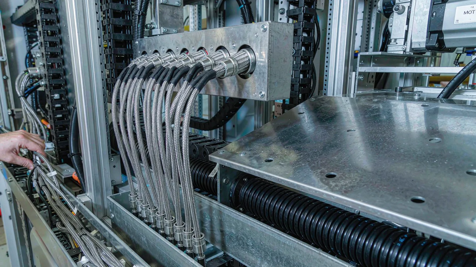
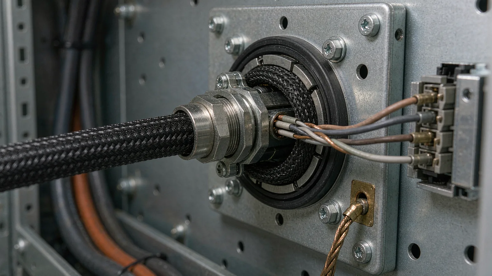
A shield works only if it is bonded correctly. For encoder cables the effective practice is a shield with high optical coverage, terminated 360 degrees at both connector or gland points, not a short pigtail twisted to a screw. A pigtail re-redirects high-frequency noise onto the shield's outside and radiates it into the very conductors it surrounds; the effect grows precisely at the frequencies where PWM drives operate. Cable glands and connector hoods designed for circumferential clamp termination make this practical, and the supplier's installation drawing should be followed rather than adapted from panel habit.
Whether to ground the shield at both ends or one end is a common argument. For encoder feedback in a machine with servo drives, both-end termination is generally the correct choice because it shorts capacitively coupled noise to chassis at the point of entry and prevents the shield from acting as an antenna; the ground-loop risk this creates is managed by the machine's equipotential bonding, not by floating the shield. Where a genuine earth loop problem exists, the fix is bonding geometry and a defined reference point, not an unterminated shield. Bond the motor frame, cable chain and cabinet earth system so that no drive return current flows through the encoder's ground path.
The signal ground itself deserves attention. Encoder electronics should be powered from a supply rail meeting the supplier's specification, separated from noisy loads, with the ground reference established at the machine's single grounding point. Datasheets specify supply tolerance and ripple; a panel that feeds the encoder from an unfiltered auxiliary output invites intermittent faults that look random because they are.
The panel wall is the boundary between the noisy power environment and the clean signal environment. Route encoder cables through glands or filtered entries immediately at the wall, terminate shields there, and keep signal and power wiring in separate looms inside the cabinet. Do not loop encoder cable around drive output chokes or alongside DC bus wiring.
Separation is the cheapest EMC measure available because it costs planning rather than hardware. Keep encoder cables at a practical distance from motor and drive power cables over their entire run: separate ducts or tray compartments, or a grounded metal partition when space forces sharing. Where a crossing is unavoidable, cross at right angles rather than running parallel. In cable chains, respect the supplier's minimum bend radius, allow the cable to move freely without tension or twist, and use chain-rated cable with the specified jacket; a mechanically damaged shield behaves as no shield at all.
Environments differ. Machine tools with high-power spindles, linear-motor stages with high acceleration currents and inspection instruments with sensitive low-level signals place different demands on separation distance and shielding. Where the machine builder cannot guarantee separation, a grounded steel channel or conduit along the shared run provides both a barrier and a known return path. The important principle is that the routing decision is made once, on the drawing, not discovered during commissioning when looms are already laced.
SENFU provides installation guidance with its encoder configurations, including cable specification, bend radius, shield termination and connector detail. Following the drawing avoids the two most common failure modes seen in the field: a shield that stops at a pigtail inside the first connector, and a feedback cable laced into the same loom as its own motor's power cable. Both are invisible in a photograph of a finished machine and both produce position jitter that no controller filter can remove without also removing real signal bandwidth.
Write the EMC acceptance check into the commissioning plan, not into a troubleshooting session. The core measurement is position jitter or signal error rate under controlled conditions: drives disabled, then drives enabled at zero speed, then across the full speed and direction range, then with the axis and its cable chain moving through real travel if the encoder is on a moving stage. Each condition isolates a coupling mechanism. If jitter appears only with drives enabled and scales with speed or switching load, look at separation and shield termination; if it appears with drives off, look at supply, grounding and nearby switched loads.
Use the controller's own diagnostics as evidence: incremental counter error registers, communication error counters on absolute interfaces, and velocity-loop noise recorded with the drive's tuning tools. Correlate events in time with contactor operations, drive enable events and mains disturbances. An oscilloscope on the differential signal pairs, observed with proper probing, can show whether common-mode excursions or differential ringing dominate, but the digital evidence from the controller is often sufficient and more reproducible.
Document the result with the same discipline as a metrology test: cable type and length, shield termination method, routing and separation achieved, grounding scheme, the measurement method, and the jitter or error-rate values per condition with a stated acceptance limit. SENFU supports this step with application engineering review of cable and grounding drawings before build, and with configuration-specific installation documents that the acceptance record can reference. A qualification file that captures EMC evidence at commissioning protects both the machine builder and the encoder supplier when a field issue later needs a root cause.
CONCLUSION
Encoder position stability is a system property: the readhead, cable, shields, grounding, routing and controller form one signal chain. Most field jitter traces back to installation decisions, pigtailed shields, shared looms, shared ground paths, that cost nothing to fix on the drawing and days to fix on the machine. Separate power from feedback, terminate shields circumferentially at both ends, ground to a single reference, and prove the installation with drives running.
For a SENFU technical review, send the encoder configuration, cable routing drawing, cabinet layout, grounding scheme and commissioning test plan. SENFU can check the installation against configuration-specific requirements and provide the documentation needed for the machine's acceptance record.
SOLUTION ROUTES
EVIDENCE CHECKLIST
FAQ
That pattern points to coupling from the drive's PWM output: capacitive or inductive coupling from motor cables, or a shared ground path. Check shield termination at both ends, physical separation from power cables, and that no drive return current flows through the encoder signal ground. Correlate jitter with speed and switching load to isolate the mechanism.
For encoder feedback in machines with servo drives, terminating the shield circumferentially at both ends is generally correct: it shorts capacitively coupled noise at the entry point and prevents the shield from radiating. One-end grounding is occasionally used for low-level analog circuits to avoid earth loops, but for digital encoder signals the loop concern is managed by proper equipotential bonding, not by floating the shield.
There is no single universal distance, but good practice keeps separate ducts or tray compartments for feedback and power over the full run, with grounded partitions where sharing is unavoidable. Where crossings occur, cross at right angles. Avoid long parallel runs in a shared duct, which is the highest-risk geometry for both capacitive and inductive coupling.
Yes. A pigtail exposes the shield's interior to coupled noise at high frequencies and re-radiates it, and the effect is worst exactly in the frequency range where PWM drives operate. Use cable glands or connector hoods with circumferential shield clamp so the braid is bonded 360 degrees at the entry point.
Measure position jitter and controller error counters under defined conditions: drives disabled, drives enabled at standstill, full speed range, and cable chain motion if applicable. Record the measurement method, cable and grounding configuration, and values per condition against a pre-agreed acceptance limit. A static test with motors unpowered does not qualify the feedback chain.
Send the encoder configuration, cable type and lengths, routing drawing with separation from power circuits, cabinet entry and shield termination plan, grounding scheme and supply details. SENFU application engineering can check the plan against configuration-specific installation requirements before build.
AUTHORITATIVE SOURCES
TECHNICAL REVIEW
Send the application, critical parameters and any drawing or process information available.
Discuss your application ↗