
Feedback chain characterization
Document the readhead signal period, configured resolution, interpolation method, output interface, counter or drive input bandwidth and the total latency from motion to servo sample.
TECHNOLOGY / PRECISION STAGE METROLOGY
How linear encoder signal quality, speed limits and interface latency shape velocity feedback quality and the servo bandwidth a precision stage can actually close.
Published
DIRECT ANSWER
Velocity feedback from a linear encoder is derived from position: the servo estimates velocity from the encoder's position increments, so the quality of the velocity signal depends on encoder resolution, signal-to-noise ratio, interpolation error and the latency of the counting and transmission chain. A stage cannot close a velocity loop significantly faster than its feedback allows — noise in the position signal becomes noise in the derived velocity, and latency adds phase lag that directly consumes stability margin.
Before tuning the servo, verify the three encoder-side limits: the maximum speed at the configured resolution (signal period times edge rate must stay within the interpolator and counter bandwidth), the noise floor of the position signal at rest and at speed, and the interface latency from readhead to drive. These set the achievable bandwidth; the mechanical plant sets the rest.
ENGINEERING CONTEXT
A precision stage vendor promises nanometer resolution and a high-bandwidth drive, but the tuned axis still hums at low level, the velocity estimate is noisy enough to force conservative gains, or the loop loses counts only at speed. The gap is rarely the drive alone: encoder-derived velocity feedback couples the encoder's electrical and interpolation behavior into the servo loop, and any of resolution, signal quality, edge-rate limits, filtering and latency can be the binding constraint. Diagnosing the loop without characterizing the feedback chain wastes tuning effort and leaves performance on the table.
Discuss your requirement ↗CRITICAL REQUIREMENTS
Document the readhead signal period, configured resolution, interpolation method, output interface, counter or drive input bandwidth and the total latency from motion to servo sample.
Verify that the maximum axis velocity keeps the encoder output frequency within the interpolator, cable and counter limits at the configured resolution, including acceleration transients.
Measure the position signal noise floor at rest and the velocity-estimate noise at operating speed, and quantify loop latency so the servo bandwidth target is chosen against real phase margin.
BUYER MATRIX
Give every shortlisted supplier the same process definition and request configuration-specific proof.
| Limit | Where it comes from | Symptom when exceeded | Design check |
|---|---|---|---|
| Maximum mechanical speed | Readhead and interpolation speed rating at the configured resolution | Lost counts, velocity glitches or fault at speed | Output frequency = velocity / signal period; check against datasheet at actual resolution |
| Signal-to-noise ratio | Optical signal amplitude, contamination, electrical noise, cable quality | Velocity jitter at rest and low speed; premature derivative action | Measure rest-position noise floor; inspect signal margins during commissioning |
| Interpolation error | Subdivision error and periodic error in the interpolation electronics | Position ripple at signal period, velocity ripple at frequency proportional to speed | Compare against published subdivision-error specification; keep residuals out of the loop gain |
| Interface latency | Serial protocol transmission, counter gating and servo sample alignment | Phase lag reduces margin; achievable bandwidth drops | Count the chain: readhead processing, transmission time, drive sampling and filtering |
| Filtering | Analog bandwidth, digital filters in interpolator or drive | Additional lag and group delay on top of latency | Document every filter; re-derive phase margin with filters included |
A linear encoder reports position. The servo's velocity estimate is built from that position signal — by differencing, by a state observer, or by a dedicated velocity loop whose gain is shaped by the same signal. Everything the encoder does electrically therefore appears in the velocity loop: resolution sets the quantization of the differencing operation, noise sets the noise floor of the estimate, periodic interpolation error injects ripple at frequencies tied to the signal period, and latency adds phase lag exactly where the loop needs margin.
This coupling is why encoder selection and servo tuning cannot be sequenced independently. An axis specified with an extremely fine resolution but a noisy or high-latency interface can close a smaller useful bandwidth than an axis with coarser, cleaner, faster feedback — because the drive must filter or reduce gains to stay stable, and filtering adds its own lag. The useful comparison is the whole feedback chain: readhead signal quality, interpolation, transmission, drive input processing and sampling, ending in the algorithm that produces the velocity command.
A practical commissioning sequence makes the chain visible: log the raw position signal at rest to measure its noise floor; command constant velocities across the operating range and log the velocity-estimate error against a stable timebase; and record the servo's response to a small velocity step at several gains. Each measurement attributes a limitation to a specific element instead of folding it into 'tuning difficulty'.
The most common encoding failure at speed is arithmetic, not physics. An encoder's output frequency is velocity divided by the signal period; at the configured subdivision, the effective edge rate rises linearly with speed, and every element downstream — interpolator, cable driver, receiver, counter input — has a maximum it will honor. Exceeding it does not usually produce a clean error: it produces missed counts, a velocity estimate that folds back, or an intermittent fault that only appears during fast traverses.
Work the arithmetic at the actual configuration, not the datasheet's headline case. A readhead may quote a maximum speed at one resolution and a much lower one at a finer subdivision; the quoted value is only valid at the stated setting. Include transients: during acceleration the instantaneous velocity is bounded by the profile, but any velocity overshoot in the loop itself, or a step command the drive executes faster than the planned profile, briefly raises the edge rate beyond the nominal maximum. A margin of headroom between the worst credible edge rate and the lowest rated limit in the chain is cheap insurance.
Cable length compounds the limit, because transmission lines and differential receivers degrade signal edges with distance. If the axis needs both high speed and long cabling, the specification conversation must include both — and the cable type, routing and shielding requirements from the encoder supplier's installation instructions become servo-relevant, not just wiring instructions.
Complete this check for every axis before closed-loop commissioning:
The velocity loop differentiates, and differentiation amplifies high-frequency content. Quantization noise from a coarse resolution, electrical noise on the analog or digital signal, and periodic interpolation error all enter the velocity estimate and, at high loop gains, reappear as audible noise, current ripple and velocity jitter at the output. The distinguishing signature is frequency: periodic error appears at a frequency proportional to velocity — tied to the signal period — while electrical noise appears regardless of motion, and quantization shows as a velocity-dependent dither.
Characterize each at rest and at speed. At rest, log position with the servo off: the noise floor and any drift belong to the feedback chain. With the servo closed at moderate gain, log the velocity command and the actual velocity: ripple at a velocity-proportional frequency indicates periodic error being amplified; broadband noise indicates electrical or quantization sources. The remedies differ. Periodic error is addressed at the source — cleaner signals, better interpolation, or software compensation of the characterized periodic term — not by raising loop gain that then fights it.
Filtering is the last resort, not the first, because every filter adds phase lag in exactly the band where the servo wants margin. When filtering is unavoidable, document it in the loop model: the filter's delay joins the interface latency in the phase-margin budget. A stage whose stability depends on undocumented drive filters is a stage whose behavior changes silently when someone 'cleans up' the configuration.
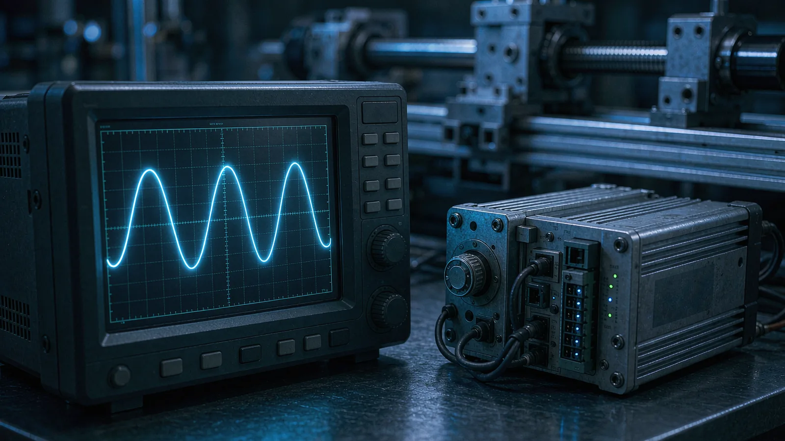
Every element between motion and the servo's use of the measurement adds delay: readhead processing, serialization and transmission for digital interfaces, counter gating, drive input filtering, and the alignment of encoder samples to servo sample instants. The total is small in milliseconds but large in phase at servo frequencies — at a 1 kHz loop, one-tenth of a millisecond is over a third of a degree of phase, and the terms accumulate. The achievable bandwidth is set by where the accumulated lag, the mechanical resonances and the noise floor together exhaust the phase and gain margin.
Set the bandwidth target from this budget rather than from aspiration. Measure or obtain each delay term from the supplier's documentation; measure the dominant mechanical resonance; then choose position and velocity loop gains whose crossover frequencies leave margin against both. When an application genuinely needs bandwidth beyond what the feedback chain allows, the specification conversation moves to the encoder interface — a faster serial protocol, a shorter transmission path, an analog interface with defined bandwidth, or a drive that timestamp-compensates the encoder sample — rather than to more tuning effort on an architecture that cannot deliver it.
Keep the evidence with the axis file: the speed-check arithmetic, the measured noise floors, the identified periodic-error signature, the delay budget and the final phase margin with all filters documented. When the axis later behaves differently, this record distinguishes feedback-chain drift from mechanical change and turns support conversations into minutes instead of days. SENFU's application engineering reviews encoder-and-drive combinations against exactly this budget for SMG-series feedback on precision stages, from output frequency limits at the configured resolution to interface latency and noise behavior.
CONCLUSION
Velocity feedback on a precision stage is derived from the encoder's position signal, so the achievable servo bandwidth is bounded by the feedback chain: output frequency limits at the configured resolution, signal-to-noise ratio, periodic interpolation error, and the accumulated latency from readhead to drive. Characterizing those limits before tuning attributes each performance ceiling to a specific element, and filtering or gain changes stop being guesses.
For a SENFU feedback review, send the axis velocity profile, encoder configuration, interface type, cable length and drive platform. SENFU application engineering can check the edge-rate arithmetic, characterize noise and latency expectations for the selected readhead and interface, and identify where a different configuration would raise the bandwidth the servo can actually use.
SOLUTION ROUTES
EVIDENCE CHECKLIST
FAQ
Divide the maximum axis velocity by the encoder signal period to get the output frequency, and compare it against the readhead's rated maximum speed at that specific resolution or subdivision. Then check the interpolator, cable and counter or drive input limits at the same frequency. The lowest rated limit in the chain, with margin for overshoot, sets the safe maximum velocity.
The velocity estimate is differentiated from the position signal, so it amplifies high-frequency content: electrical noise, quantization dither and periodic interpolation error. Higher resolution does not remove electrical noise or periodic error. Measure the rest-position noise floor and the velocity-proportional ripple frequency to identify which source dominates before changing gains or filters.
A filter reduces noise amplitude but adds phase lag, which consumes the stability margin the loop needs for bandwidth. Filtering is appropriate when the noise source cannot be fixed at the origin, and it must be documented in the loop model because its delay joins the interface latency in the phase-margin budget.
Significantly, because the lag accumulates in phase at the loop crossover. At a 1 kHz bandwidth, 0.1 ms is more than a third of a degree of phase; several such terms add up. The total latency from motion to servo sample should be part of the bandwidth budget, and applications needing high bandwidth should specify interfaces and drive processing with low and well-characterized delay.
Velocity and current ripple at a frequency proportional to velocity, tied to the encoder signal period, often accompanied by position ripple at the same scale. It is distinguished from electrical noise by its velocity dependence. The remedy is at the source — signal quality, interpolation quality or characterized software compensation — rather than higher loop gain, which fights the error and adds noise.
Send the maximum velocity and acceleration profile, the encoder model and configured resolution, the interface type and cable length, the drive or counter platform, and the observed symptom — noise, lost counts, limited bandwidth. SENFU application engineering can verify the speed limits at the actual configuration and assess the noise and latency behavior of the feedback chain.
AUTHORITATIVE SOURCES
TECHNICAL REVIEW
Send the application, critical parameters and any drawing or process information available.
Discuss your application ↗