
Verified feedback chain
Encoder signal quality confirmed before tuning: differential signal levels, jitter with drives disabled, cable EMC practice per supplier installation drawing, and correct resolution and direction configuration in the drive.
TECHNOLOGY / SERVO FEEDBACK TUNING
Tune servo loops on direct-drive linear motor stages with optical encoder feedback: loop architecture, bandwidth versus resolution limits, noise injection into torque, notch filtering and a commissioning procedure that produces verifiable results.
Published
DIRECT ANSWER
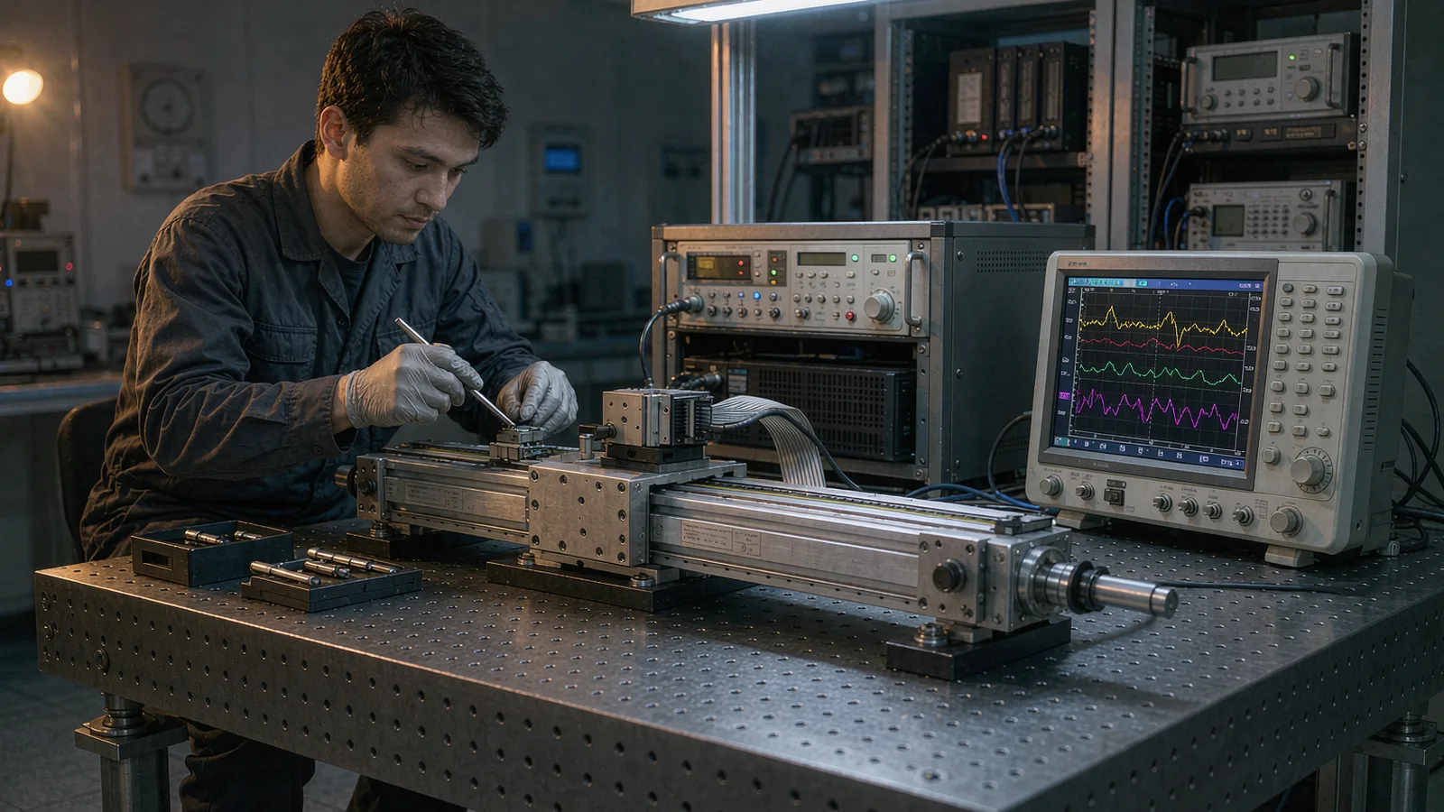
On a direct-drive linear stage the encoder is not only a position sensor; it is the velocity signal, the integrator for position, and the path through which every noise source becomes motor torque. Tuning therefore starts from the feedback chain, not from the gain knobs: verify signal quality and jitter with drives off, set the velocity loop bandwidth to what the encoder's effective noise floor supports, then raise the position loop, and only then apply feedforward and notch filters for structural resonances.
The governing trade is simple: servo bandwidth cannot exceed what feedback noise permits, because every bit of position noise that enters a high-gain loop is differentiated into velocity error and amplified into audible, heating-producing torque ripple. Measure the noise floor first, choose gains that keep amplified noise within drive and thermal limits, and use feedforward rather than raw gain to reduce tracking error. That sequence produces stages that are both accurate and quiet; the reverse sequence produces machines that oscillate, overheat and then get blamed on the encoder.
ENGINEERING CONTEXT
Direct-drive stages remove transmission backlash and compliance, so in theory they support servo bandwidths that geared axes never reach. In practice, teams raise gains until the stage sings: an audible tone from torque ripple, current draw at standstill, and micron-scale jitter that looks like an encoder fault. Because the amplifier drives current proportional to loop error, any noise on the feedback signal at standstill is converted directly into force. The dilemma is that the symptom appears electrical, the suspicion falls on the sensor, and the encoder gets replaced, while the actual constraint was the loop structure: a velocity estimate differentiated from quantized or noisy position, gains set above what the noise floor supports, and a structural resonance waiting at the new bandwidth. Resolving it requires a method that separates feedback noise, loop gain and mechanical resonance before touching a single gain value.
Discuss your requirement ↗CRITICAL REQUIREMENTS
Encoder signal quality confirmed before tuning: differential signal levels, jitter with drives disabled, cable EMC practice per supplier installation drawing, and correct resolution and direction configuration in the drive.
Knowledge of the stage's structural resonances from a frequency response or current-step test, moving mass, friction level and any cable-chain forces, so loop bandwidth targets and notch settings are chosen against data.
Defined cascade structure (current, velocity, position), bandwidth targets per loop, feedforward plan, filter settings and explicit limits on allowed standstill current and noise-induced torque ripple.
Recorded step, ramp and tracking responses, standstill jitter with drives enabled, thermal check after sustained operation, and acceptance limits agreed before tuning begins.
BUYER MATRIX
Give every shortlisted supplier the same process definition and request configuration-specific proof.
| Limiting factor | Symptom in the stage | Diagnostic evidence | Engineering response |
|---|---|---|---|
| Encoder noise floor | Audible torque ripple, heating at standstill, velocity noise | Standstill current draw with drives enabled and no motion command; jitter scales with loop gain | Verify signal quality and grounding; lower velocity bandwidth; use position-domain filtering per supplier guidance |
| Quantization / interpolation error | Fine jitter or limit cycling at standstill, stair-stepped micro-motion | Jitter amplitude comparable to effective resolution; repeater pattern in position trace | Check interpolation settings and signal amplitude; confirm scale condition; accept resolution as physical limit rather than fighting it with gain |
| Structural resonance | Oscillation at a specific frequency when bandwidth raised, gain-dependent ringing | Frequency response or current-step test showing a resonance peak; oscillation frequency independent of gains once excited | Notch or low-pass filtering at the identified frequency; mechanical stiffening; keep crossover well below resonance |
| Feedback latency | Reduced achievable phase margin; instability at modest bandwidths | Bandwidth ceiling below expectation with clean signals; phase lag consistent with filtering and transmission delay | Reduce unnecessary filtering in the feedback path; use drive settings for the encoder interface per specification |
| Velocity estimate quality | Noisy velocity loop output, poor tracking on smooth moves | Velocity trace noise far above encoder jitter; acceleration-dependent torque noise | Use the drive's observer or higher-rate interface as specified; avoid over-differentiating quantized position in external controllers |
A linear motor applies force directly to the payload without gears, screws or couplings. That removes the compliant elements which both excite and mask disturbance in geared axes, and it means the servo loop sees the payload's true dynamics: nearly pure mass, with the structural resonances of the base and carriage as the first complications. In this configuration the encoder provides everything. There is no rotary sensor on the motor to give velocity; velocity is estimated, in the drive, from the encoder's position signal. Position error becomes velocity error, velocity error becomes current command, and current command becomes force. The feedback chain is therefore inside the torque path, not merely reporting to it.
This has a consequence that experienced servom engineers internalize and newcomers rediscover painfully: noise on the feedback signal is converted into real force. Position noise differentiated by the velocity loop appears as an alternating force command at the noise frequencies. On a direct drive with no reduction ratio to attenuate it, that force acts directly on the payload and its reaction on the stator. The audible whine of an over-tuned linear stage is literally the encoder's noise floor, multiplied by loop gain and transduced into the frame. The same mechanism produces standstill heating, because the drive supplies current to make a force that fights noise rather than moving mass.
The correct conclusion is not that optical encoders are unsuitable for direct drive; it is that the feedback chain must be engineered to the same standard as the mechanics. That includes the EMC installation practice for cables and grounding, the signal amplitude and interpolation configuration, and the drive's input filtering set per the encoder supplier's specification. An encoder installed per its drawing delivers a noise floor the drive can be tuned against; an encoder installed with pigtailed shields delivers a noise floor that no gain set can rescue.
Begin with drives disabled and the axis at rest. Record the position signal from the controller over a defined window, using the same interface and filtering the servo loop will see. This standstill trace is the feedback chain's noise floor in the position domain: its amplitude should be consistent with the encoder's effective resolution and the known installation conditions. Then enable the drive with zero velocity command and record standstill current. The difference between these two states is the loop's own amplification of noise into torque, and it is the single most informative number in the whole tuning session. If standstill current is significant, no amount of later gain polishing will produce a clean stage; correct the feedback installation first.
Tune the current loop to the drive's standard commissioning values for the motor, then the velocity loop. Set velocity bandwidth conservatively, verify the stage tracks a low-jerk ramp without velocity noise beyond the encoder's noise floor, and only then raise the position loop. Use feedforward, velocity and acceleration, to attack tracking error during moves rather than demanding it all from loop gain; feedforward adds error correction without adding noise amplification at standstill, which is exactly the trade a direct-drive stage wants. Where the controller offers them, keep the loops cascaded in the documented structure rather than improvising parallel paths, because later diagnosis depends on knowing what each loop contributes.
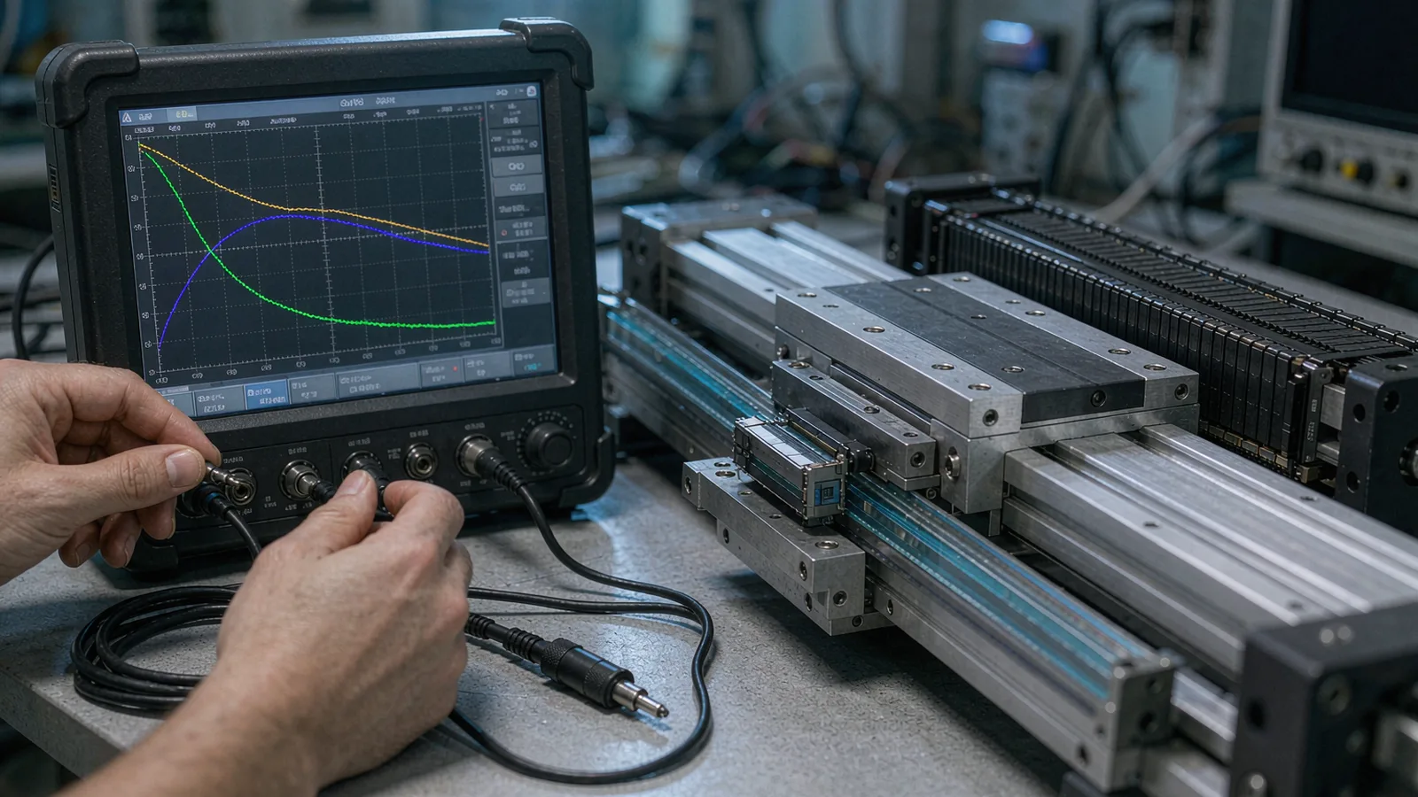
Resonance comes last because it is revealed by bandwidth, not caused by it. As velocity bandwidth rises, a structural mode of base, carriage or cable chain will eventually enter the loop's neighborhood and show up as ringing after moves or oscillation at a fixed frequency. Identify that frequency from the ringing itself or from a frequency-response measurement, then apply the drive's notch filtering at it, narrowest filter that works, and verify the result with the same step test. Keep the final crossover a safe factor below the first significant resonance; where the resonance sits too low for the target bandwidth, the answer is mechanical stiffening or mass reduction, not filter heroics.
Each step gates the next; skipping ahead hides causes.
After tuning, the stage's residual errors sort into categories that should be kept distinct in the record. Static repeatability at standstill reflects the encoder's resolution, its noise floor through the tuned loop, and the mechanical isolation of the axis; micron-range values here are normal and correct for typical optical encoder resolutions, and trying to squeeze them lower with gain produces the noise amplification described above. Tracking error during moves reflects bandwidth, feedforward accuracy and disturbance rejection; it improves with the tuning quality and with smooth motion profiles. Contouring or stitching accuracy at the application level then adds geometric contributions, Abbe offsets, straightness and angular errors, which no servo tuning addresses; those belong to the mechanical design and to compensation tables.
This separation protects the project from the most common escalation error: treating a geometric or thermal error as a tuning failure and cycling gain changes that degrade the noise behavior without touching the real cause. When the record keeps standstill jitter, tracking error and measured geometric error as separate numbers with separate acceptance limits, each deviation points to its own owner. Velocity-dependent position error that correlates with direction, for example, usually indicates either backlash-like effects in cable drag or an interpolation error contribution from the scale, both of which have established test procedures rather than tuning remedies.
SENFU supports this discipline with configuration-specific data for its encoder families: effective resolution and interpolation error behavior, recommended drive interface settings and filtering, and installation requirements that establish the noise floor the tuning assumes. For direct-drive stage builders, application engineering can review the feedback chain together with the drive's tuning results, providing the boundary between what feedback can deliver and what the loop may demand of it. That boundary, documented, is the difference between a stage that stays tuned and one that is retuned after every commissioning dispute.
Close the commissioning with a record that a later engineer can act on: the tuning parameters with their software versions, the measured noise floor and standstill current, step and ramp responses with stated measurement settings, notch frequencies and widths, and the acceptance limits agreed at the start. This is the baseline against which drift is judged. Servo performance degrades slowly in service through mechanical change, cable wear in the chain, contamination on the scale, or drive parameter edits during maintenance, and each of these leaves a signature in the recorded metrics before it becomes a production problem.
A short periodic check, standstill jitter and standstill current with the same method as commissioning, catches most of these signatures in minutes. A rising standstill current at unchanged gains points at growing feedback noise or mechanical friction; a change in standstill jitter amplitude points at the encoder chain; a new ringing frequency points at mechanical change such as a loosened mount or added payload. The periodic record converts tuning from a one-time event into a maintained property, which matters on direct-drive stages precisely because their performance ceiling is set by the feedback chain that the record watches.
Documenting the feedback chain as part of the acceptance record, encoder configuration, interface settings, cable practice and measured noise floor, also protects the supplier relationship. When a field issue later arises, the boundary between encoder behavior and loop tuning is already evidenced, and diagnosis proceeds from data rather than from replacement parts. SENFU's application documentation is structured to support exactly this evidence chain from installation through acceptance into service life.
CONCLUSION
Direct-drive linear stages concentrate the whole servo problem into the feedback path: the encoder's noise floor, resolution and installation quality define how much loop gain is usable, and every decibel of bandwidth bought beyond that is paid back in torque ripple, heat and jitter. Start from a verified signal chain, set bandwidths against the measured noise floor, use feedforward for tracking error, and treat resonance with data and narrow filters rather than gain reductions that cost performance everywhere else.
For a SENFU technical review, send the stage and drive architecture, encoder configuration, tuning records and acceptance limits. SENFU application engineering can check the feedback chain against the encoder's specified behavior, advise on interface settings and filtering, and help establish the acceptance and periodic-verification records that keep the stage tuned through its service life.
SOLUTION ROUTES
EVIDENCE CHECKLIST
FAQ
On a direct drive, loop error becomes force. Feedback noise entering the closed loop is amplified into an alternating force command, producing audible torque ripple and standstill heating. Measure standstill current with zero command: if it is significant, verify the feedback chain first, signal levels, cable EMC, shield termination, grounding, before adjusting gains.
The ceiling is set by the encoder's effective noise floor, the drive's filtering and latency, and the stage's first structural resonance. A disciplined method measures the noise floor, tunes conservatively upward, and stops where noise amplification into torque or a resonance appears, keeping crossover a safe factor below the first significant mechanical mode.
Often it is simply the resolution and noise behavior of the feedback chain amplified by the loop, not a defect. Compare the jitter amplitude against the encoder's effective resolution and the drive's filtered input. If jitter matches the resolution order of magnitude and standstill current is normal, the loop is behaving physically and lower jitter requires better resolution or lower bandwidth, not part replacement.
Prefer feedforward. Velocity and acceleration feedforward reduce tracking error during moves without increasing the loop's noise amplification at standstill, which is the critical trade on direct drives. Raise loop gain only as far as the noise floor and resonances permit, and rely on feedforward for the remainder of the dynamic error.
When the oscillation occurs at a fixed structural frequency that enters the loop as bandwidth rises. Identify the frequency from ringing or a frequency-response test, apply a narrow notch at it, and re-verify the step response. Notches cost no static performance, but they are compensation, not repair: a resonance that drifts with payload or temperature needs mechanical attention or a wider filter with its attendant phase cost.
Send the stage architecture and drive platform, encoder model and interface configuration, cable and grounding practice, tuning records with standstill measurements, and the acceptance limits you intend to apply. SENFU application engineering can review the feedback chain against the encoder's specified behavior and advise on settings and verification records.
AUTHORITATIVE SOURCES
TECHNICAL REVIEW
Send the application, critical parameters and any drawing or process information available.
Discuss your application ↗