
Abbe offset stated per axis
Name the distance between the encoder measuring axis and the functional point for each axis, in the plane where the sensitive rotation acts, and keep it in the stage drawing as a controlled dimension.
TECHNOLOGY / ENCODER METROLOGY
Abbe error converts angular motion into linear position error through the offset between the measuring axis and the point of interest. This guide sets out the Abbe principle, the offset-times-angle arithmetic, where pitch and yaw come from, the design countermeasures that work, and how to place Abbe terms inside a stage error budget.
Published
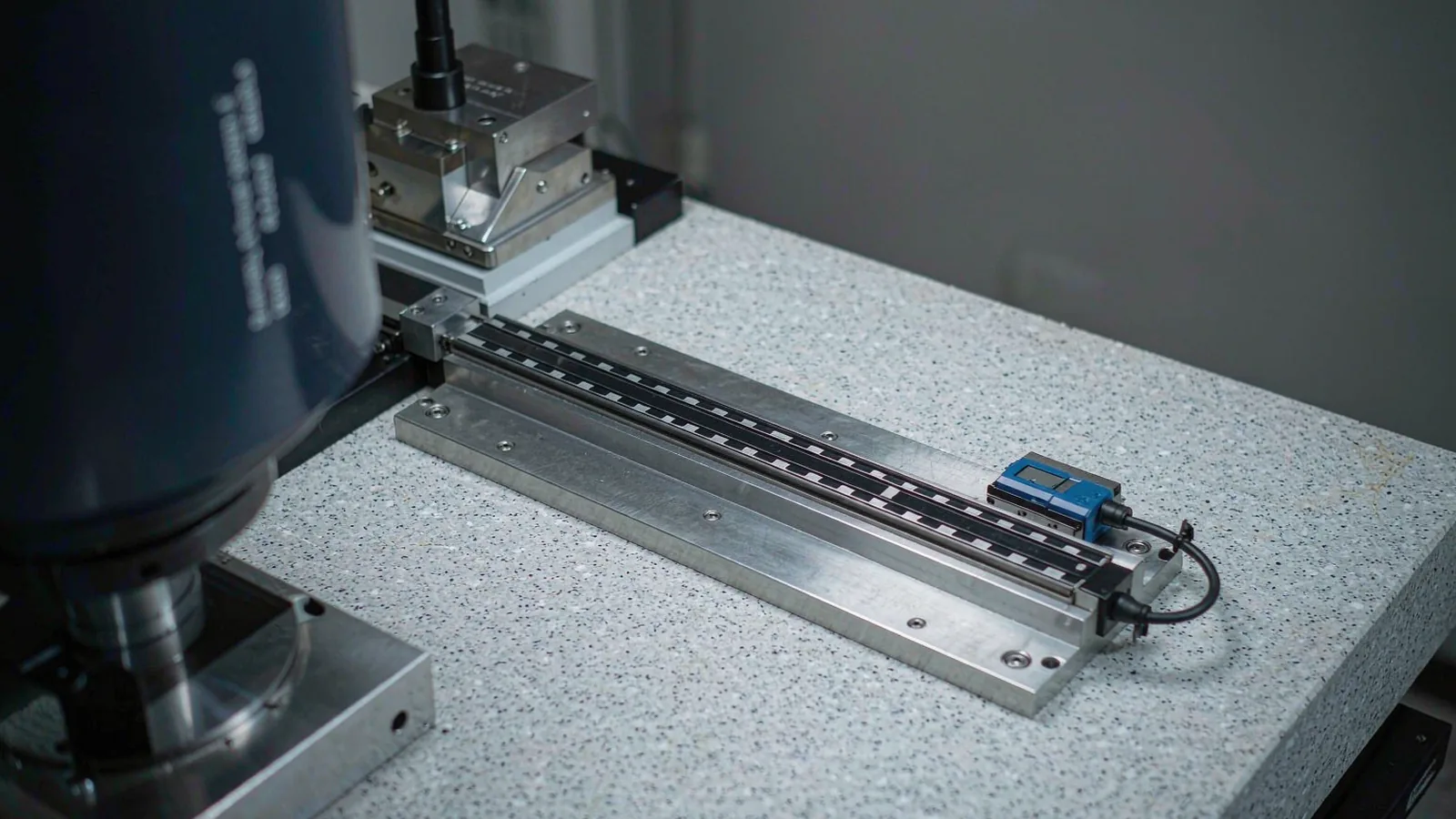
DIRECT ANSWER
Abbe error is the linear position error created when the measuring axis of an encoder is offset from the point whose position the machine cares about, and the carriage rotates by a small angle as it moves. The magnitude is the offset multiplied by the sine of that angle, which for the small angles seen on precision stages is simply offset times angle in radians. The useful unit rule follows directly: one microradian acting across one millimetre of offset produces one nanometre, so a 100 mm offset with 10 microradians of pitch or yaw produces about a micrometre.
There are only three ways to reduce it. Shrink the offset by moving the scale closer to the functional point or redesigning the stage so the two are coplanar; remove the angular motion by stiffening the structure, balancing the drives and controlling moment loads; or measure the angle and compensate, which requires the pitch and yaw to be repeatable and measured with enough resolution. A stage specification should state the Abbe offset per axis, the permitted pitch and yaw over travel, the load case those figures assume, and the acceptance method used at the functional point.
ENGINEERING CONTEXT
Abbe error is the most common reason a stage with an excellent encoder still fails a tolerance at the tool. The encoder is honest; it reports the position of the scale exactly. The problem is geometry: the scale sits where the mechanical design could put it, usually beside or beneath the carriage, while the process happens at a point tens or hundreds of millimetres away. Every microradian of pitch and yaw in the guideway is multiplied by that distance and delivered to the workpiece as a position error the encoder cannot see. Because the term is geometric rather than electronic, it appears in no encoder datasheet, and it is usually discovered at acceptance, where the cure is no longer a drawing change but a compensation table of uncertain validity.
Discuss your requirement ↗CRITICAL REQUIREMENTS
Name the distance between the encoder measuring axis and the functional point for each axis, in the plane where the sensitive rotation acts, and keep it in the stage drawing as a controlled dimension.
Specify permitted rotation over the full travel under the real load case, in microradians, rather than only specifying straightness or flatness in micrometres.
Require a measured pitch and yaw map over travel using an autocollimator, electronic level or angular interferometer, with the instrument and traceability stated.
Verify accuracy where the process actually happens, with the stage loaded and warm, so the Abbe contribution is included in the result rather than excluded by the test setup.
BUYER MATRIX
Give every shortlisted supplier the same process definition and request configuration-specific proof.
| Term | Geometry that creates it | How it behaves | Reduction route |
|---|---|---|---|
| Abbe error, first order | Offset between the scale measuring axis and the functional point, combined with pitch or yaw of the carriage | Linear in the offset and linear in the angle; one microradian across one millimetre gives one nanometre, so it dominates on long offsets | Reduce the offset, make the scale and the work point coplanar, or measure and compensate the angle |
| Cosine error, second order | Angular misalignment between the scale measuring direction and the direction of travel | Grows with the square of the misalignment angle, so a fraction of a degree is small over a metre but not always negligible on long travel | Align the scale to the travel direction during installation and verify with a bidirectional length comparison |
| Scale shape imposed by mounting | Straightness and flatness errors of the mounting surface, plus clamping distortion and adhesive shrinkage | Appears as a long-period position error that follows the mounting surface rather than the grating | Machine the mounting datum, control clamping torque and adhesive, and map the axis after mounting |
| Load-induced tilt | Moment loads from the payload, cable drag, drive thrust offset or acceleration reaction deflecting the structure | Changes with payload position and with the motion profile, so it is not removed by a no-load calibration | Balance the drive thrust line, stiffen the structure, route cables to minimise moment, and measure under the real load case |
| Thermal offset drift | Temperature gradients moving the structure between the scale and the functional point, and changing the offset itself | Slow drift correlated with warm-up and gradients rather than with position | Separate the metrology loop from the force loop, control the environment, and state the reference temperature |
| Compensation residual | Imperfect measurement of pitch and yaw, plus non-repeatable angular motion between passes | Reduces the mean error and leaves scatter; the residual is bounded by the repeatability of the angle, not by the encoder | Measure angular repeatability before committing to compensation, and revalidate at defined intervals |
Ernst Abbe stated the principle in 1890: to measure a dimension accurately, the measuring system must be placed in line with the dimension being measured. Applied to a stage, the encoder scale should lie along the same line as the displacement of the point the machine cares about. Any separation creates a lever arm, and any rotation of the carriage acts on that lever arm to produce a displacement at the functional point that the encoder does not report.
James Bryan later generalised the rule for cases where collinearity is mechanically impossible, which is most of them. His formulation says that if the measuring axis cannot pass through the functional point, then either the guideway must be free of angular motion, or the angular motion must be measured and compensated. That second clause describes what most precision stages actually do, and it is why the angular repeatability of a stage matters as much as its straightness.
The error is the offset multiplied by the sine of the rotation angle, and for the angles a real stage produces the small-angle approximation is exact enough: error equals offset times angle in radians. A convenient unit rule drops out of it. One microradian across one millimetre gives one nanometre, so a 50 mm offset with 20 microradians of yaw gives a micrometre, and a 200 mm offset with 5 microradians gives the same micrometre. Offsets that look mechanically trivial therefore carry errors that dominate a sub-micrometre budget.
Two rotations matter for a linear axis, and each has its own offset. Pitch acts through the vertical offset between the scale plane and the work plane. Yaw acts through the horizontal offset measured sideways from the scale to the point of interest. A complete stage needs both terms written for each axis, because a design that eliminates one is frequently silent about the other.
Pitch and yaw are not encoder defects; they are the response of the mechanical system to its own operation. Guideway or bearing geometry produces a baseline angular variation along travel. Applied loads, including the payload, produce deflection proportional to compliance. A drive thrust line that misses the centre of mass produces a moment that changes with acceleration, so tilt differs between acceleration and deceleration. Cable drag adds moments that vary with position, and thermal gradients bend the structure slowly.
This is why angular error measured unloaded, cold and at constant speed is not the angular error the machine sees. The measurement has to reproduce the load case, the duty cycle and the thermal state, or the Abbe term derived from it will be optimistic. Treat pitch and yaw as functions of position, load, acceleration and temperature rather than as a single number, and map them under the conditions the process will run.
Cosine error comes from the measuring direction of the scale not being exactly parallel to the direction of travel, and it grows with the square of that misalignment angle. A misalignment visible to the eye still produces a small error over a short travel, which is why cosine error is usually the lesser term on compact stages and still worth checking on long ones, particularly where the scale was mounted against a datum that was not machined for it.
The shape the mounting surface imposes on the scale is separate and frequently larger. A linear scale is flexible enough to follow the surface it is bonded or clamped to, so straightness and flatness errors in the mounting face, clamping distortion and adhesive shrinkage all appear as long-period position error after installation. These terms are not Abbe error either, but they are placement-driven and reduced by the same discipline: a machined datum, controlled clamping torque, a defined adhesive process, and a map taken after mounting.
The most effective measure is geometric: put the measurement where the work is. Placing the scale in the plane of the functional point removes the offset rather than compensating for it, which is why coplanar architectures and scales mounted close to the work surface are worth their mechanical inconvenience. Where the work point sits above the carriage, a bridge or metrology-frame arrangement can carry the scale closer to it, at the cost of structure and envelope.
Where the offset cannot be removed, symmetry helps. Two readheads or two scales on opposite sides of the axis, averaged, cancel the first-order contribution of a pure rotation, because one channel sees a positive error and the other an equal negative one; this is standard practice on wafer stages and long-travel gantries. The remaining route is compensation: map pitch and yaw, multiply by the offset and subtract. It works when the angular motion is repeatable and fails quietly when it is not, so measure angular repeatability before adopting it.
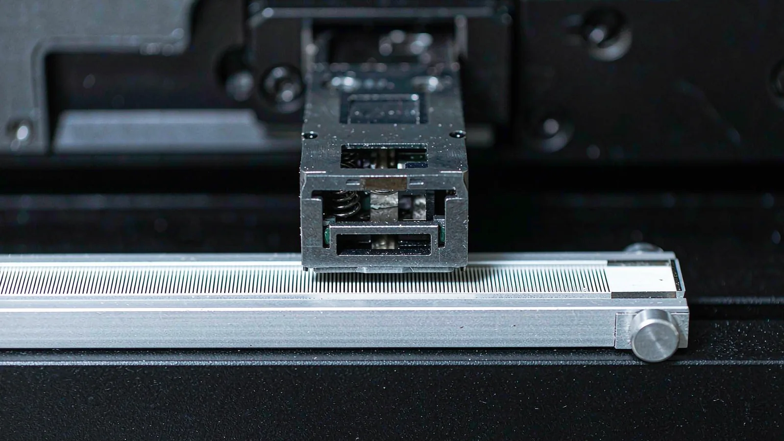
Pitch and yaw are measured with an autocollimator and a mirror on the moving carriage, with electronic levels, with the angular optics of a laser interferometer, or with two displacement sensors on a known base. Whichever method is used, the result should be a map over travel rather than a maximum, because the Abbe term at the position where the process runs is what matters. Build the budget backwards from the tolerance: subtract guide straightness, scale graduation, interpolation and thermal terms, then divide the remainder by the offset to get the angular budget in microradians.
Write that into the specification as clauses. State the offset per axis as a controlled drawing dimension, state permitted pitch and yaw in microradians with the payload, acceleration and thermal condition assumed, and state whether the machine relies on geometry, dual-channel averaging or compensation, including how often a compensation map is revalidated. The acceptance test then mirrors it: an angular map under the defined load case, a position error map taken at the functional point rather than at the readhead, and a bidirectional repeatability measurement with the temperature recorded.
CONCLUSION
Encoder placement is a metrology decision that happens to be made by a mechanical designer. The Abbe term is simply offset times angle, and with one microradian across one millimetre costing one nanometre, the offsets found in ordinary stage layouts convert ordinary angular motion into position errors that no encoder specification can absorb. Decide early whether the design will remove the offset, cancel it with symmetric channels or compensate it from a measured angle, then write the offset, the angular budget and the acceptance method into the specification so the decision survives contact with the build.
EVIDENCE CHECKLIST
FAQ
It is the linear position error produced when the encoder measuring axis is offset from the point whose position matters and the carriage rotates slightly as it travels. The error equals the offset multiplied by the sine of the rotation angle, which for small angles is offset times angle in radians.
Use the unit rule: one microradian across one millimetre gives one nanometre. A 100 mm offset with 10 microradians of pitch or yaw gives about a micrometre. Whether that matters depends on the tolerance at the functional point, which is why the offset belongs in the error budget.
No. Abbe error is first order, growing linearly with offset and angle. Cosine error comes from the scale measuring direction not being parallel to the travel direction and grows with the square of that misalignment angle, so it is usually the smaller term over short travel.
Yes, if the angular motion is repeatable: map pitch and yaw along travel, multiply by the offset and apply a correction. The residual is bounded by the repeatability of the angle, so measure that first and revalidate the map at defined intervals.
Remove the offset by placing the scale in the plane of the functional point. Where that is impossible, average two symmetric channels to cancel the first-order rotation term, stiffen the structure to reduce the angle itself, and only then fall back on compensation.
AUTHORITATIVE SOURCES
TECHNICAL REVIEW
Send the application, critical parameters and any drawing or process information available.
Discuss your application ↗