
Resolution as a servo requirement
Derive the needed increment from following error, velocity ripple and quantization noise targets at maximum speed, and confirm the output frequency stays inside the interface and controller limits.
TECHNOLOGY / ENCODER METROLOGY
High resolution does not make an axis accurate. This guide separates resolution from accuracy in optical encoders, splits the error budget into interpolation, scale, installation and thermal terms, and shows how to write both specifications so a machine requirement is actually met.
Published
DIRECT ANSWER
Resolution is the smallest position increment an encoder reports. Accuracy is how close that report is to the true position under stated conditions. They are connected only through the error budget: a 1 nm output increment sitting on a scale with a few micrometres per metre of graduation error, a fraction of a micrometre of interpolation error and a mounting-induced cosine error still reports a position that is wrong by micrometres. Specify resolution from what the servo needs for smooth low-noise motion, and specify accuracy from the tolerance the machine must actually hold.
The practical way to write both is to keep four lines separate. State resolution as a digital increment at a defined interface and at the maximum travel speed, because output frequency, not optics, sets that limit. State scale accuracy as a mapped deviation over the full travel at a reference temperature, not as a single number per metre. State interpolation or subdivision error separately, as an amplitude in nanometres. State installation, Abbe and thermal terms as a budget the machine design owns. Then require a mapped accuracy report against a traceable reference with the interpolation contribution identified, plus signal margin evidence at the worst case of travel and readhead gap.
ENGINEERING CONTEXT
Most encoder specifications are read as a single column: the smallest number wins. In practice the smallest number is usually resolution, and it is the cheapest quantity to improve because it lives in electronics. Accuracy lives in the scale, the mounting, the structure and the environment, and it costs real money and real design attention. A buyer who asks for 1 nm because it sounds safe often receives an encoder whose interpolation factor has been raised to the point where output frequency limits the axis speed, where quantization noise has been replaced by interpolation noise, and where the accuracy of the installed axis has not improved by a single nanometre. The result is a slower machine with a more impressive datasheet. The opposite failure is just as common: a stage designed around a headline resolution with no error budget at all, which passes a short-travel demo and fails the first full-travel map. Both failures come from the same root cause, treating two different quantities as one.
Discuss your requirement ↗CRITICAL REQUIREMENTS
Derive the needed increment from following error, velocity ripple and quantization noise targets at maximum speed, and confirm the output frequency stays inside the interface and controller limits.
Require scale accuracy stated as a deviation over the full travel at a reference temperature, measured against a traceable reference with the mapping interval disclosed.
Ask for subdivision error as an amplitude in nanometres within one signal period, measured under defined signal amplitude, gap and alignment conditions rather than quoted as a percentage alone.
Allocate straightness, alignment, Abbe offset, scale substrate expansion and readhead gap stability to the mechanical design, and verify them at acceptance rather than assuming the catalogue covers them.
BUYER MATRIX
Give every shortlisted supplier the same process definition and request configuration-specific proof.
| Error term | What creates it | Signature in the data | Reduction route |
|---|---|---|---|
| Interpolation or subdivision error | Amplitude, offset and phase imperfections in the analogue signal, plus quantisation inside the interpolator | Short-period error repeating once per scale pitch, visible as cyclic ripple in a position error map | Improve signal quality, gap stability and contamination control; a higher interpolation factor does not remove it |
| Scale graduation error | Manufacturing deviation of the grating or its substrate, plus the shape the substrate imposes after mounting | Long-period error across the travel that does not repeat within a signal period | Choose a higher accuracy class, control the mounting substrate, or map and compensate |
| Installation error | Readhead gap and alignment errors, scale straightness after mounting, Abbe offset combined with pitch and yaw | Error that grows with travel and changes when the mounting or load changes | Fix the mechanical datum, minimise the Abbe offset, and verify with a straightness map after mounting |
| Thermal and environmental error | Mismatch between scale, structure and workpiece expansion, plus refractive and dimensional drift | Slow drift correlated with temperature and warm-up rather than with position | Choose the scale material and datum strategy deliberately, control the environment, and state the reference temperature |
| Interface and timing error | Output frequency limits, cable delay, controller sampling and latency | Apparent position lag or lost counts that appear only at high speed | Check the resolution-versus-speed matrix before selecting the interpolation factor |
| Repeatability and hysteresis | Bearing and guide behaviour, reversal error, coupling compliance | Non-repeatable scatter between approaches to the same target | Separate repeatability from accuracy in the specification and measure bidirectional approach |
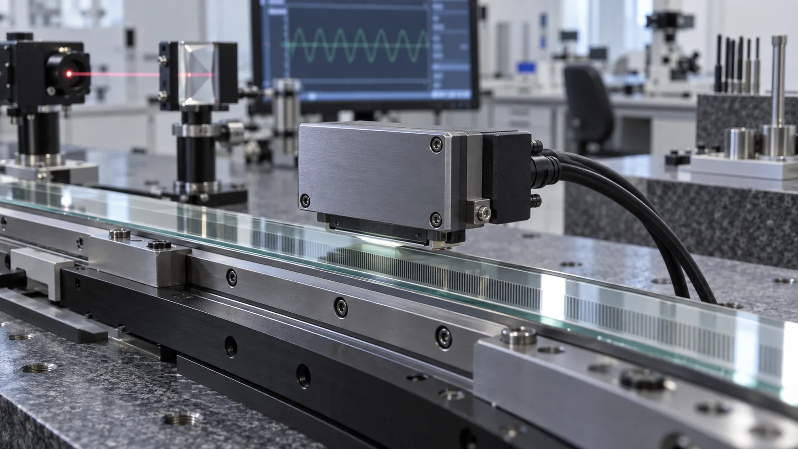
An optical encoder generates a periodic signal as the readhead moves across a scale with a fixed pitch. The electronics divide that period into a number of steps and present a digital increment. Nothing about the physical measurement improves when the division factor goes up; the same optical signal is simply being reported in finer slices. The physical measurement is bounded by how faithfully the scale pattern represents distance and by how cleanly the readhead converts it into an electrical signal.
The practical limit on resolution is therefore not optical, it is electrical. Every count has to leave the encoder through an output interface at a rate that the cable, the receiver and the controller can accept. A 20 micrometre pitch interpolated to 1 nm produces twenty thousand counts per pitch, so a stage moving at one metre per second would need a billion counts per second. No differential line driver and no motion controller does that. In real configurations the resolution column and the maximum speed column are coupled, and the honest specification is always a matrix, not a single figure. This is why resolution should be selected from the servo requirement rather than maximised.
Accuracy describes the deviation between the reported position and the true position under stated conditions. Four families contribute, and they behave differently enough that lumping them together destroys the analysis. Interpolation error is short-period, repeating once per signal period. Scale graduation error is long-period, appearing as a slow deviation across the travel. Installation error includes the readhead gap and alignment, the straightness the mounting substrate imposes on the scale, and any Abbe offset between the measuring point and the point of interest. Thermal and environmental error drifts with temperature and warm-up rather than with position.
Each family has its own reduction route and its own cost. Interpolation error responds to signal quality, gap stability and contamination control. Scale error responds to the accuracy class you buy and to how well the substrate supports the scale after mounting. Installation error responds to mechanical design and assembly discipline. Thermal error responds to material selection and control of the environment. A buyer who improves only one line and declares the axis improved has usually spent money on the cheapest line and left the dominant one untouched.
Raising the interpolation factor does three things, and only one of them is desirable. It produces a finer reported increment, which helps the velocity loop when quantization noise is the limiting term. It raises the output frequency for a given speed, which can force a reduction in maximum speed or a coarser resolution at speed. And it exposes interpolation error more clearly: the same percentage of a signal period now appears as a smaller nanometre figure, but the underlying signal imperfection that created it is unchanged, and the finer increment makes short-period ripple more visible to the servo and to the acceptance map.
There is also a measurement trap. A finer increment makes noise look like resolution. If short-period error and electrical noise dominate, adding resolution gives a display that jitters in the last digit while the true position is no better known. Servo behaviour can degrade because the controller reacts to noise that carries no information. The useful target is the coarsest increment that still keeps quantization below the noise floor of the rest of the loop, typically an order of magnitude finer than the positioning tolerance the process requires, and no finer.
Four questions expose almost every weak specification. At what speed and output frequency is the stated resolution valid? Is the accuracy figure a scale deviation measured over the full travel, or a per-metre figure from which the buyer is expected to extrapolate? Is interpolation error quoted as a percentage of a signal period or as an amplitude in nanometres, and under what signal amplitude and gap? At what reference temperature, and with what mapping interval, was the accuracy measured?
A supplier who answers all four with numbers and conditions is describing a product. A supplier who answers with a single headline resolution and a single accuracy number is describing a marketing position. The distinction matters most when the machine requirement is tight, because at that point the acceptance test will be written from the same specification, and whichever terms were left vague will be the terms that fail.
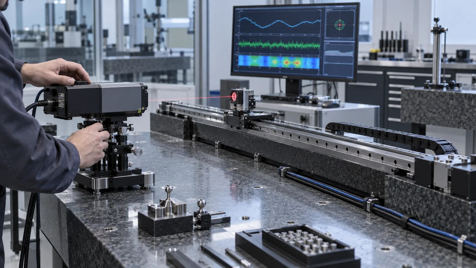
Start at the point of interest. Write down the tolerance the process must hold at the tool, the wafer or the workpiece, then work backwards through the mechanical chain to the encoder. Along the way, subtract what the machine design owns: guide straightness, pitch and yaw, structural compliance under load, thermal growth between the scale and the point of interest, and the Abbe offset that converts angular error into linear error. What remains is the allowance the encoder and its installation must share.
Split that remainder between scale accuracy and interpolation error, and give each a number with a condition attached. Then check the resolution question separately, from the motion profile: maximum speed, acceleration, following error target and acceptable velocity ripple. If the resolution needed for smooth motion is finer than the accuracy budget can justify, that is normal and fine; resolution and accuracy are allowed to differ by orders of magnitude. If the resolution needed at maximum speed exceeds the interface limit, the answer is not a finer interpolator but a coarser pitch, a different interface, or a two-speed strategy.
Write resolution and accuracy as separate clauses. The resolution clause names the digital increment, the interface, and the maximum speed at which it is valid. The accuracy clause names the mapped deviation over the full travel, the reference temperature, the reference instrument and its traceability, and the mapping interval. Add a third clause for interpolation error as an amplitude in nanometres, and a fourth for signal margin at the worst-case travel position and readhead gap.
The acceptance test then follows the clauses directly: a full-travel position error map against a traceable reference, an interpolation error measurement made under defined signal conditions, a signal amplitude and margin record across travel, and a repeatability measurement taken bidirectionally so reversal behaviour is visible. Suppliers who build the complete feedback chain can supply these as one coherent package rather than as four disconnected documents, which is usually the difference between a specification that can be verified and one that can only be argued about.
CONCLUSION
Resolution and accuracy answer two different questions, and a good encoder specification answers both explicitly. Choose the increment from the servo and the interface, choose the accuracy class from the mapped tolerance the machine must hold, and keep interpolation, installation and thermal terms as separate lines with their own evidence. Stages specified this way tend to be less impressive on paper and considerably better on the floor, because every number in the datasheet is one the installation can actually be held to.
EVIDENCE CHECKLIST
FAQ
Not by itself. Resolution is the reporting increment. Accuracy is set by scale graduation, interpolation quality, mounting, alignment and thermal behaviour. Raising the interpolation factor reports the same measurement in finer slices and can even make short-period error more visible.
Every interpolated count has to leave the encoder through its output interface. A finer increment produces more counts per millimetre, so the same speed requires a higher output frequency. The real limit is the interface, the cable and the controller, not the optics.
The coarsest increment that keeps quantization below the noise floor of the rest of the loop, typically about an order of magnitude finer than the positioning tolerance your process requires. Going finer adds interface load and noise without improving the true position.
As a mapped deviation over the full travel, measured against a traceable reference, with the reference temperature and mapping interval stated. A single per-metre figure without a measurement method cannot be used as an acceptance criterion.
Interpolation error is short-period and repeats once per scale pitch; it comes from signal imperfections inside the readhead electronics. Scale error is long-period and comes from the grating manufacturing and from the shape the mounting substrate imposes. They have different reduction routes and should be budgeted separately.
AUTHORITATIVE SOURCES
TECHNICAL REVIEW
Send the application, critical parameters and any drawing or process information available.
Discuss your application ↗