
Angular error budget
Translate encoder resolution and accuracy into radial placement error at the end effector.
APPLICATION / SEMICONDUCTOR HANDLING
Choose rotary position feedback for wafer handlers by mapping angular error, cycle behavior, payload inertia, interface and cleanroom evidence to the complete mechanism.
Published
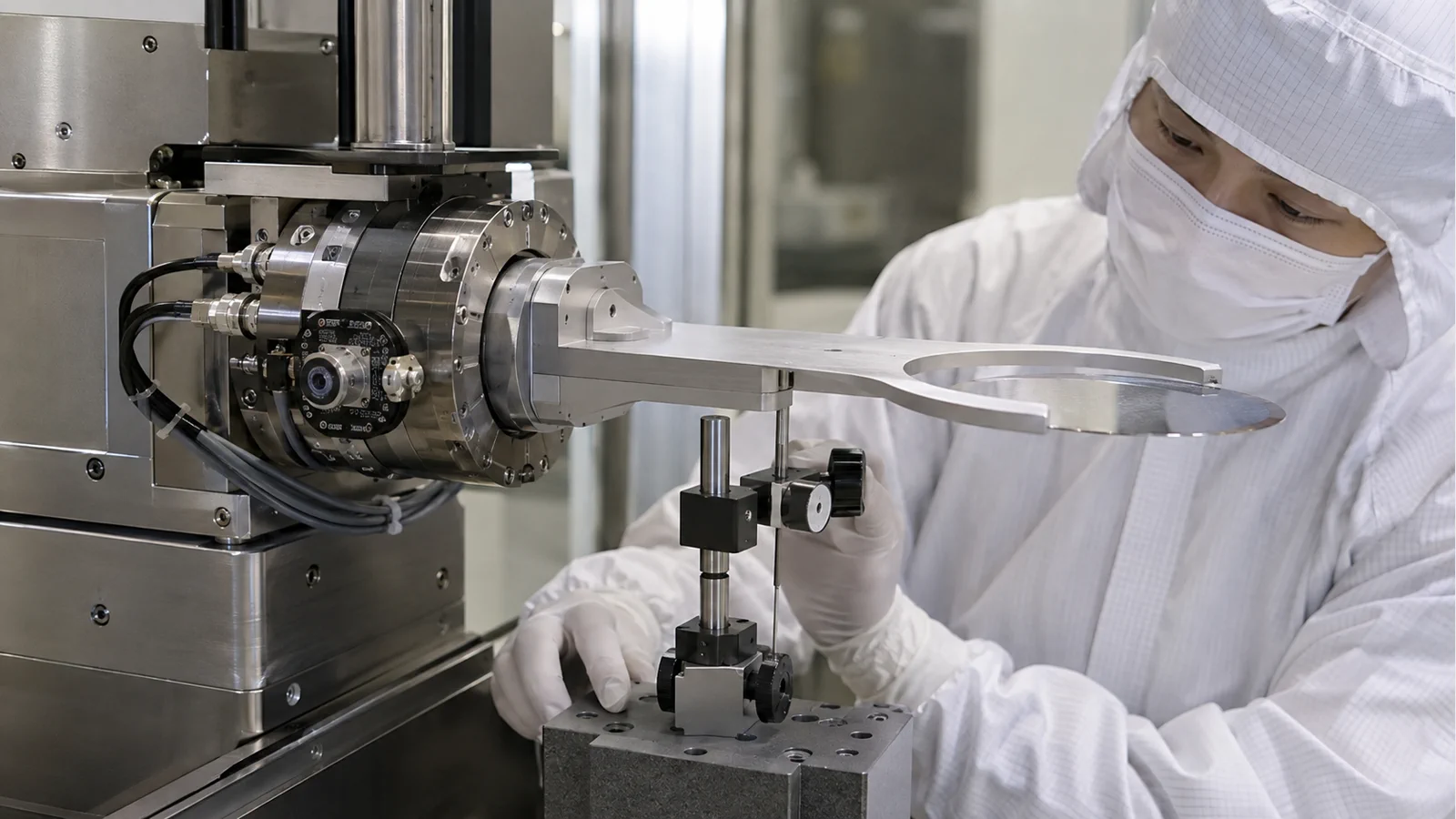
DIRECT ANSWER
Select a rotary encoder for a wafer handler from the angular error budget and the handoff sequence, not from line count alone. Define shaft or hollow-bore geometry, payload inertia, acceleration, settling time, repeatability, allowable angular error at the wafer edge, temperature, cleanliness, cable routing and the controller interface. Then map those requirements to a model-specific drawing and test plan.
For a wafer-handling axis, a small angular error can become a larger placement error at an end effector. Separate encoder resolution from shaft accuracy, bearing runout, coupling error and robot compliance. Ask the supplier for the configured output, maximum speed, interface timing, environmental limits and an acceptance method that measures the end effector or wafer coordinate. A cleanroom label by itself does not prove suitability for the actual robot envelope or process.
ENGINEERING CONTEXT
Wafer handling turns angular feedback into a coordinate and timing problem. The encoder must survive rapid pick-and-place cycles, report a stable angle through acceleration and settle within the robot's handoff window while the mechanism remains clean, serviceable and mechanically repeatable.
Discuss your requirement ↗CRITICAL REQUIREMENTS
Translate encoder resolution and accuracy into radial placement error at the end effector.
Define speed, acceleration, settling, indexing positions and the cycle-time margin.
Confirm shaft, bore, coupling, bearing loads, envelope, cable route and service access.
Specify cleanliness, temperature, pressure, materials and controller interface.
BUYER MATRIX
Give every shortlisted supplier the same process definition and request configuration-specific proof.
| Question | Evidence | Risk if unanswered |
|---|---|---|
| Where is angle measured? | Shaft, joint or end-effector datum drawing | Robot reports motor angle while the wafer is offset |
| How fast is the cycle? | Speed, acceleration, settle time and output update rate | The servo loses feedback margin during handoff |
| What is the real angular error? | Accuracy, runout, coupling and calibration data | Line count is mistaken for placement accuracy |
| Does the interface fit? | Signal format, cable, clock or receiver limits | Noise or latency creates false index positions |
| Can it be serviced cleanly? | Materials, connector and replacement procedure | Maintenance introduces particles or lost alignment |
Begin with the wafer coordinate, not the encoder catalogue. If the end effector reaches a radius from the rotary joint, angular error becomes a tangential placement error at that radius. Add the effects of coupling compliance, bearing runout, arm flexure, payload inertia and any calibration transformation. This lets the team decide whether the encoder is closing the main position loop, providing a secondary check or simply supplying a homing and indexing reference.
Document every handoff position and approach direction. A handler may pick a wafer from a cassette, rotate it, align a notch and place it on a chuck. Each event can have a different settling requirement and a different sensitivity to backlash. Give the supplier the actual radius, motion profile and required repeatability so the encoder configuration is reviewed at the process point rather than at the shaft alone.
A rotary encoder can report many counts per revolution while the shaft angle remains limited by scale accuracy, interpolation, eccentricity, bearing runout and coupling alignment. Resolution helps the controller observe small changes; it does not remove mechanical error. Put the encoder terms and the mechanism terms on separate rows of the error budget and identify which ones can be calibrated.
When comparing incremental and absolute devices, keep the same distinction. An absolute output can make a restart sequence faster, while an incremental output may fit an existing differential receiver and high-rate loop. The correct choice follows the robot's recovery and safety sequence. Request configuration-specific angular accuracy, interface timing and reference-mark behavior instead of comparing protocol names in isolation.
Wafer handlers often trade speed against vibration and settling. The encoder output must remain valid during acceleration, deceleration and a short settle window, while the motor and reducer cope with the payload inertia. Provide peak speed, acceleration, commanded move, load inertia, control-loop period and allowed settle time. If the system uses a gearbox, identify the output-side angle that matters and include transmission compliance.
Ask how output frequency, interpolation, serial frame time or analog bandwidth change with the selected resolution. A finer setting can increase the signal-processing burden. Validate the complete axis using the same cable length and controller that will be installed. Do not use an unloaded bench speed as a production promise for a loaded, cleanroom robot.
The mechanical drawing should show shaft or bore tolerances, mounting face, datum, coupling, allowable misalignment and service clearance. Eccentric mounting can create a once-per-revolution error even when the encoder is electrically perfect. A flexible coupling can isolate motor misalignment but also add torsion and hysteresis. For a hollow-bore device, check clamping loads and the rotor's balance at the operating speed.
Plan the cable route through the moving joint. Strain at the connector, repeated torsion, drag-chain contact and proximity to motor phases can create intermittent feedback faults. Define a replacement method that preserves the angular datum. The supplier's installation drawing and recommended coupling arrangement are evidence to include in the design review, not documents to request after the robot is built.
A wafer handler may operate inside a controlled enclosure, under purge or near vacuum load locks. Define pressure, temperature, cleaning chemistry, particle limits, lubricant restrictions, cable jacket, connector materials and the maintenance procedure. ‘Cleanroom compatible’ should be tied to a model and configuration with evidence; it should not be a general assumption made from a product category.
If the encoder is outside the vacuum boundary but coupled through a feedthrough, qualify the feedthrough and thermal path separately. If it is inside, request outgassing and bakeout information for the exact materials. Keep the same environmental conditions in the acceptance test so the feedback result represents the production installation.
Map the encoder's output to the controller input, cable length, shield termination and diagnostic handling. Differential incremental signals need a compatible receiver and a defined reference or index routine. Absolute serial feedback needs a known frame, clock, latency and error response. The startup sequence should define when angle is valid and when the robot is allowed to move.
Run EMC and recovery tests with the motors, valves and switching supplies operating. Monitor missed counts, CRC or alarm flags, index repeatability and the time required to re-establish a valid coordinate after power loss. A graceful recovery sequence is a buyer requirement because a lost wafer or an unnecessary re-home can cost more than the encoder itself.
Use an independent angular or coordinate reference to map the assembled axis. Test every programmed handoff, both approach directions, a representative payload and the temperature state used in production. Measure repeatability at the wafer or tool interface, and record the encoder value, reference value, settling time and alarms. The result should identify whether the residual is feedback, mechanics or calibration.
Retain raw data and the mechanism revision. If a coupling, gripper or cable is replaced, the team can compare the new map with the original baseline. ISO 230-2's discipline around direct measurement and repeatability is a useful model even when the final acceptance coordinate is defined by semiconductor equipment requirements rather than a machine-tool test alone.
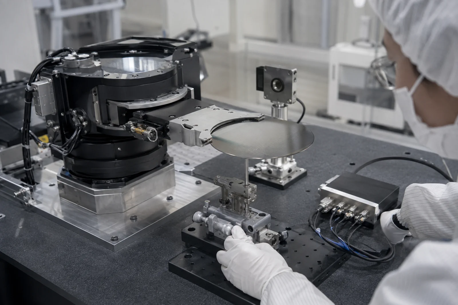
Send every shortlisted supplier the same joint angle, radius, payload, motion profile, interface, environment, installation drawing and acceptance sequence. Ask for guaranteed, typical, calculated and process-dependent values to be labelled separately. Include the replacement and calibration plan because a handler is a production subsystem, not a one-time laboratory experiment.
SENFU can review an optical encoder architecture against the documented product family and the mechanism data. A useful response will identify the model, configuration, mounting and evidence required. If a proposal only repeats line count, maximum speed or ‘high precision’ without the end-effector test, it has not closed the buyer question.
CONCLUSION
Rotary encoder selection for wafer handling is a joint error-budget, dynamic and cleanroom decision. Define the process coordinate, match the output to the controller, and verify the assembled end effector with an independent reference under the real cycle.
SENFU can review the motion profile, mechanical drawing, environment and interface and identify the product evidence required before procurement. The result should be a traceable axis configuration, not just a line-count comparison.
SOLUTION ROUTES
EVIDENCE CHECKLIST
FAQ
Specify the wafer-point error and repeatability first, then use line count and configuration-specific accuracy to close the budget. Line count alone does not describe shaft, coupling or robot compliance.
No. Absolute feedback can simplify startup recovery, while incremental feedback may fit an established high-rate receiver and homing sequence. Compare the complete safety and recovery behavior.
Provide temperature, pressure or purge, cleaning chemistry, particle limits, cable and connector constraints, lubricant restrictions and maintenance access.
Use an independent angular or coordinate reference at the end effector, test both directions and representative payloads, and retain encoder, reference, settling and alarm data.
A model number is not enough. Send the joint drawing, radius, payload, profile, interface, environment and repeatability target so the configuration can be checked.
AUTHORITATIVE SOURCES
TECHNICAL REVIEW
Send the application, critical parameters and any drawing or process information available.
Discuss your application ↗