
Measurand definition
State whether the test judges the encoder alone, the encoder plus coupling, or the complete rotary axis, and define the angle reference datum and sign convention.
TECHNOLOGY / SUPPLIER QUALIFICATION
Verify rotary encoder accuracy claims with a documented test setup, error separation, environment control and acceptance evidence before qualifying a supplier.
Published
DIRECT ANSWER
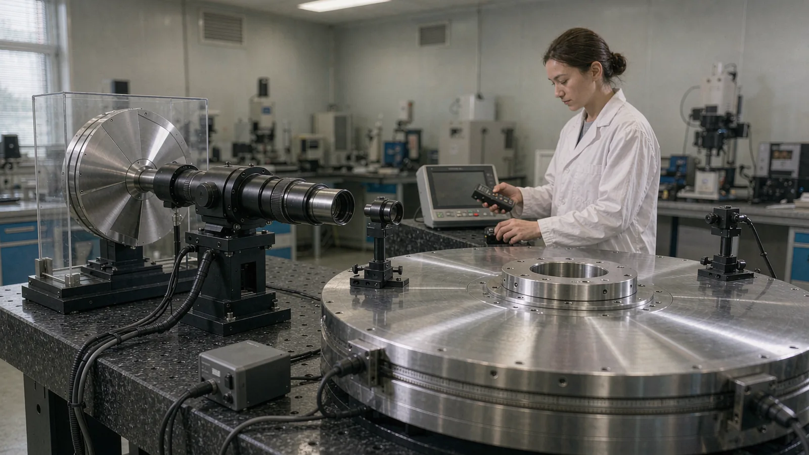
Verifying an angular encoder accuracy claim means measuring installed axis angle against a traceable angular reference over the full circle, under controlled environment, with a stated uncertainty and decision rule. Practical setups include a comparator or dividing head in the lab, a calibration ring or polygon with autocollimator on or near the target axis, and self-calibration methods such as multiple-head error separation.
The result of a single pass is not the encoder accuracy. Repeatability, eccentricity, coupling error, interpolation error, thermal drift and reference uncertainty all contribute, so the protocol must separate those terms, record the test configuration and document residuals by angle, direction and cycle. Suppliers should be asked which claims are guaranteed versus typical, and the acceptance limits should be written before the first measurement is taken.
ENGINEERING CONTEXT
A rotary encoder datasheet accuracy figure is measured under conditions the buyer rarely reproduces: a specific coupling, mounting, drive, temperature and reference instrument. Installed on a machine axis, eccentricity, shaft runout, bearing wander, thermal gradients and electronics noise add to the scale error. Without a written verification protocol, procurement compares numbers measured in different coordinate systems and cannot defend an acceptance decision when an axis later fails to meet process targets.
Discuss your requirement ↗CRITICAL REQUIREMENTS
State whether the test judges the encoder alone, the encoder plus coupling, or the complete rotary axis, and define the angle reference datum and sign convention.
Select a reference instrument with calibration uncertainty at least three to five times finer than the limit under test, with a documented calibration chain.
Specify temperature range, rate of change, vibration, and warm-up state, because several arc-seconds of drift can appear from uncontrolled thermal conditions.
Fix the statistical metric (peak-to-peak, systematic, random component), number of cycles, directions and pass/fail rule before testing begins.
BUYER MATRIX
Give every shortlisted supplier the same process definition and request configuration-specific proof.
| Setup | Best for | Typical uncertainty | Watch for |
|---|---|---|---|
| Encoder comparator with master disk | Production screening of absolute accuracy and eccentricity | Tenths of an arc-second with a high-grade master | Master disk calibration validity and head-to-master alignment |
| Dividing head / precision rotary table | Step-wise comparison on a bench or installed axis | Sub-arc-second for precision tables | Backlash and index uncertainty of the dividing device |
| Calibration polygon + autocollimator | Discrete-angle absolute verification on the target axis | Fractional arc-second at defined facets | Only sampled angles; facet count limits coverage |
| Multi-head error separation (self-calibration) | Full-circle systematic error without a better master | Limited by head noise and repeatability | Separates harmonic content only if head placement captures it |
| Precision turntable with angle interferometer | Continuous high-resolution angular comparison | Sub-arc-second with careful setup | Air refractive index, dead-path and alignment errors |
Before choosing instruments, write down the measurand. If the buyer's risk is that a positioning stage misses a photolithographic overlay target, the test should judge the complete rotary axis in a representative mounting, not a bare encoder clamped to a lab motor. If the risk is incoming-quality escape from a component lot, a comparator test of the encoder alone may be correct. Mixing the two leads to disputes, because an encoder that meets its datasheet in a laboratory comparator can still perform poorly on a machine with an imperfect coupling or eccentric mounting.
Next define the accuracy metric precisely. Many encoder specifications quote a periodic-error-limited accuracy after harmonic compensation, while others quote full-scale absolute angle accuracy including eccentricity and mounting terms. Record whether the specification applies before or after electronic compensation, at which temperature, with which coupling, and whether the readhead is single or dual. Two figures that look comparable in a datasheet table can differ by an order of magnitude once the fine print is compared.
Fix the acceptance rule in writing: how many positions, how many full revolutions, how many directions, what statistical metric and what happens when a result falls within measurement uncertainty of the limit. Writing the rule after seeing the data destroys the value of the test for supplier qualification, because the decision becomes negotiable.
The reference instrument and its calibration chain dominate the credibility of the verification. National metrology institutes describe angle realization through primary standards such as angle gauges and rotary tables with interferometric readout, and traceability requires an unbroken chain in which each calibration contributes to the combined uncertainty. For machine-level verification, the buyer rarely needs NMI-level performance, but the reference uncertainty must remain small relative to the limit under test, typically by a factor of three to five, otherwise the acceptance decision is dominated by the instrument rather than the encoder.
A comparison table of practical setups is provided above. For high-volume incoming inspection of rotary encoders, an encoder comparator with a calibrated master disk is usually the most efficient. For verifying an installed axis on a machine tool or inspection instrument, a calibration polygon with autocollimator or a precision indexing table often fits the geometry better. Multi-head self-calibration techniques described in metrology literature can separate the systematic full-circle error of a divided circle from head noise without needing a better master, provided the head placement is chosen so the target harmonics are observable.
Whichever reference is selected, record its calibration certificate number, uncertainty statement, environmental conditions of calibration, and recalibration due date. An expired or unstated reference calibration invalidates the qualification evidence regardless of how carefully the rest of the test was executed.
Angular measurements have their own version of Abbe error: if the reference and the encoder scale do not share the same axis, axial and radial motion of the shaft appears as angle error. Coupling compliance, misalignment and shaft runout convert into periodic error at once and twice per revolution. A verification protocol should either eliminate these terms by design or measure and report them separately, because otherwise the encoder is blamed for an installation effect the supplier cannot control.
Angle error and thermal drift are not independent. Encoder scale and body expansion, spindle growth, air refractive index in interferometric setups and autocollimator drift all change with temperature. A laboratory that drifts one degree Celsius during a test can contribute arc-second-level bias to the result. Define the temperature band, the maximum rate of change, the soak time before measurement, and log ambient temperature, encoder electronics temperature and reference temperature on the same clock as the angle data.
Vibration and air movement matter, particularly for optical autocollimator paths and interferometer setups. Record floor vibration state, nearby rotating machinery, and whether the test was run inside an enclosure. For electronics, allow the encoder and counter to reach their specified warm-up before recording, because oscillator and LED stabilization often shift readings for the first tens of minutes. A verification run that ignores warm-up produces a systematic offset that will reappear on every future machine and will be indistinguishable from encoder error.
Finally, decide and record the electrical noise environment. Switching power supplies, motor drives and long unshielded encoder cables can add angle jitter that inflates the random component of the measurement. If the lab test environment is much quieter than the machine, note the difference, because the installed axis will need the EMC practice described in cable routing and grounding guidance to reproduce the bench result.
Structure the measurement so that independent error sources can be separated. A typical sequence: measure mechanical runout and coupling alignment first, then record at least two full revolutions in each direction at a defined angular step. Reverse-direction passes separate backlash and direction-dependent hysteresis from repeatable systematic error. Repeat cycles at stabilized temperature allow drift terms to be identified as time trends rather than folded into the accuracy figure.
For periodic error analysis, fit a harmonic model to the residuals and report the amplitude of the dominant one-per-revolution and two-per-revolution components separately from peak-to-peak residual error. Eccentricity shows up at one per revolution; readhead or coupling misalignment often contributes at two per revolution. Reporting these separately lets the machine builder decide whether an installation correction or a dual-head scheme is the right remedy instead of rejecting the encoder.
For self-calibration, literature on divided-circle and rotary-table calibration, including work published by national metrology institutes on error separation techniques, shows that several appropriately placed reading heads can make the systematic disk error observable without a better reference. The buyer's protocol should document the head angles, the separation method and the harmonic order actually recovered, because a separation scheme that misses harmonics will under-report the systematic error and overstate the encoder's accuracy.
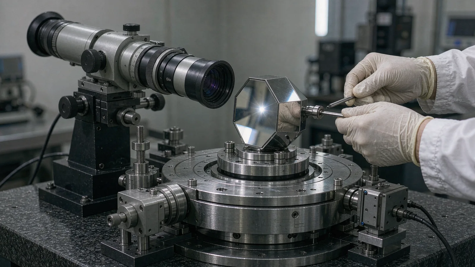
A supplier qualification package should let a third-party engineer reconstruct the test. Record the exact encoder part number, firmware and interpolation settings, coupling type and installation, mounting drawing revision, reference instrument serial and calibration status, environment logs, raw angle data, analysis method with software revision, and the residuals by angle, direction and cycle. Screenshots of curve fits are not evidence; export the underlying data with units and timestamps.
Attach the decision record: the pre-agreed acceptance limits, the measured metric values, the reference uncertainty, and the explicit pass or fail statement. If a result falls near the limit, the decision rule determines the outcome; noting how the borderline case was resolved, and whether additional independent cycles were run, protects the buyer if the decision is later audited. NIST guidance on metrological traceability emphasizes that traceability alone does not make an uncertainty adequate; the documented uncertainty budget and decision rule are what make the verification defensible.
Feed the evidence back into supplier management. If the verification passes with margin, the configuration, environment and test recipe become the reference acceptance test for future lots. If it fails, the separated error terms tell the supplier whether the issue is scale error, eccentricity, electronics or installation, which turns an argument into an engineering conversation. SENFU supports this workflow by providing configuration-specific accuracy statements, calibration and mounting documentation, and application engineering review of the proposed test setup before the first measurement is taken.
CONCLUSION
A defensible angular encoder accuracy verification pairs a traceable reference with a written measurand definition, environment control, error separation and a pre-agreed acceptance rule. The separated residuals, not a single peak-to-peak number, are what allow a buyer to distinguish scale error from eccentricity, coupling and installation effects.
For a SENFU technical review, send the rotary axis drawing, target accuracy, coupling and mounting plan, environment conditions and proposed reference setup. SENFU can review the protocol, confirm which accuracy statements apply to the exact configuration, and supply the documentation needed for the qualification file.
SOLUTION ROUTES
EVIDENCE CHECKLIST
FAQ
Define the measurand and acceptance limits first, then compare installed axis angle against a traceable reference such as a calibration polygon with autocollimator, a precision indexing table or an angle interferometer. Record multiple revolutions in both directions at stabilized temperature, separate eccentricity and coupling effects from scale error, and document the reference uncertainty with the results.
Error separation is a family of techniques in which the systematic error of a divided circle or rotary reference is distinguished from the error of the instrument under test, often by using multiple reading heads at chosen angles or reversal methods. Done correctly, it recovers full-circle harmonic error without needing a reference better than the device being measured; the head placement must make the target harmonics observable.
A dominant one-per-revolution component usually indicates eccentricity between the encoder disk axis and the rotation axis, or a radial offset in the measurement setup. Check mechanical runout, mounting fit and coupling alignment before attributing the error to the encoder scale itself.
A common practice is a test uncertainty ratio of at least three to one, meaning the reference uncertainty is three to five times smaller than the tolerance being verified. Below that ratio, a meaningful fraction of the acceptance decision is determined by the reference instrument rather than the encoder, and the decision rule must account for it explicitly.
Yes. Scale and body expansion, spindle growth, air refractive index in optical setups and electronics drift all vary with temperature and can contribute arc-second-level bias. Specify a temperature band, soak time and rate-of-change limit, and log temperatures on the same clock as the angle data.
Send the axis drawing, encoder configuration under consideration, target accuracy and metric, coupling and mounting plan, environment specification, proposed reference instrument and acceptance rule. SENFU application engineering can confirm applicable accuracy statements for the exact configuration and identify documentation needed for qualification.
AUTHORITATIVE SOURCES
TECHNICAL REVIEW
Send the application, critical parameters and any drawing or process information available.
Discuss your application ↗