
Pattern statistics extracted
For each layout class, quantify written area fraction, number of distinct figures, edge count, minimum feature, and repeating-cell content. These numbers—not machine class—predict writing time under each strategy.
TECHNOLOGY / E-BEAM LITHOGRAPHY WRITING STRATEGY
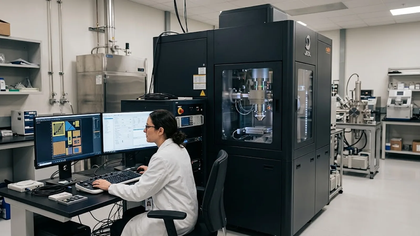
Every electron-beam lithography system spends its writing time through one of a few deflection strategies—raster scanning, vector scanning, variable-shaped beams, or cell projection. This guide explains how each strategy spends beam time, how the choice interacts with shot count, dose, and proximity effects, and how to match the writing strategy to real pattern statistics instead of a datasheet number.
Published
DIRECT ANSWER
In electron-beam lithography, the writing strategy is the rule that decides where the deflection system sends the beam and where it does not. Raster scanning sweeps the beam in a fixed serpentine path across the whole field and turns the blanker on only where the pattern exists; vector scanning steers the beam directly to each pattern element and skips empty space entirely; variable-shaped-beam and cell-projection systems go further by exposing many pixels—or a whole pattern primitive—in a single flashed shot.
The strategy determines how writing time scales with your layout. Raster time depends mostly on field area and pixel clock, regardless of pattern density, which suits uniform grids and dense repeating structures. Vector time depends mostly on shot count and move-settle overhead, which suits sparse layouts but punishes patterns made of millions of tiny edges. Shaped-beam systems trade flexibility for throughput by exposing with rectangles or projected cells instead of a single spot. Choose by counting shots and dwell times for your actual layout, not by comparing machine classes.
ENGINEERING CONTEXT
System quotations describe capability in strategy vocabulary—raster, vector, shaped beam—and buyers translate those labels into an expected writing time that the actual layout then contradicts. A vector machine quoted for fast writing on sparse patterns slows dramatically on a dense grating whose every edge becomes a separate shot; a raster machine with a fixed pixel throughput turns out to spend the same hours on a chip that is 2 percent filled as on one that is fully packed. Neither number is wrong; each describes a different relationship between pattern content and exposure time. The consequences reach beyond schedule: the strategy that minimizes shot count may maximize shot noise at fixed dose, and the strategy that fills fields uniformly may expose more resist than the pattern needs, feeding proximity effects. Because writing strategy is fixed at machine architecture while layouts change every project, the defensible evaluation compares candidate strategies against representative patterns from the intended process—counting flashes, dwell times, and stage moves—before the purchase order and again before every throughput commitment.
Discuss your requirement ↗CRITICAL REQUIREMENTS
For each layout class, quantify written area fraction, number of distinct figures, edge count, minimum feature, and repeating-cell content. These numbers—not machine class—predict writing time under each strategy.
State the dose window, target linewidth, and linewidth-roughness tolerance. Strategy choice changes shot count and dwell time, which changes shot-noise exposure and the margin available for process variation.
Require writing-time estimates for representative layouts under stated resolution, beam current, and step-and-repeat conditions, with the shot-count assumptions shown so they can be re-checked when patterns change.
Confirm how the design file is fractured into shots or cells for the chosen strategy, how fracturing affects pattern fidelity, and who owns the conversion toolchain and its parameters.
BUYER MATRIX
Give every shortlisted supplier the same process definition and request configuration-specific proof.
| Aspect | Raster scan | Vector scan | Variable-shaped beam | Cell / character projection |
|---|---|---|---|---|
| Beam delivery | Fixed serpentine sweep across the field; blanker gates the beam on pattern pixels only | Beam steered figure-by-figure to written geometry; empty space skipped | Flashable rectangle of variable size exposes many pixels per shot | Projected mask cell or character exposes a complete primitive per shot |
| Writing time driver | Field area and pixel clock; largely independent of pattern density | Shot count and move-settle overhead; sensitive to edge count | Total exposed area and rectangle count | Cell library coverage and repetition rate of primitives |
| Best-fitting patterns | Dense, uniform arrays; gratings; full-field coverage | Sparse layouts; varied geometry; few-layer R&D work | Large-area dense patterns with regular shapes | Highly repetitive layouts such as memory-like arrays |
| Flexibility cost | Uniform coverage regardless of content; over-exposed area management needed | Performance degrades as figure count grows | Shape repertoire limited to rectangles and their combinations | New geometries require new cells; library maintenance burden |
| Typical domain | Mask writing, fixed-format production | Nanodevice R&D, photonics, quantum layouts | High-throughput industrial lithography | Mask writing and repetitive semiconductor layers |
An electron-beam system exposes resist by placing flashes of electrons at defined positions, and every architecture answers the same three questions differently: where does the beam go next, how large is one exposure event, and how much empty space does the beam visit on the way? Raster scanning answers with a fixed serpentine path—the beam crosses the entire writing field on a pixel grid, and the blanker switches it on only where the pattern lives. Vector scanning answers by steering the beam directly to each figure in the pattern and dwelling there; unwritten space is never visited. Shaped-beam and cell-projection architectures change the size of the event itself, replacing the single spot with a variable rectangle or a projected pattern primitive, so that one flash can deposit what a Gaussian-spot system needs thousands of shots to deliver.
The strategy is fixed in the machine's deflection, blanking, and column architecture; the layout is fixed in the design file; and writing time emerges from the fit between the two. That is why the same machine can write one chip in forty minutes and its neighbor in fourteen hours with identical resist and dose: the difference is shot count, dwell distribution, and move-settle overhead. Evaluating a writing strategy therefore means evaluating how it maps pattern content onto exposure events—a property of the pair, never of the machine alone.
Raster scanning is the strategy of mask writers and fixed-format production tools, and its virtue is predictability. Because the beam follows the same serpentine path every time, writing time is essentially a function of field area and pixel clock: a field of given size takes a given time whether it is 3 percent or 90 percent filled. Deflection control is correspondingly simple—the path is precomputed, the blanker pattern streams alongside it, and dynamic errors accumulate in a regular, calibratable way. For dense, uniform patterns such as photomask arrays, gratings, and full-coverage levels, the raster approach uses its beam time almost entirely on written pixels, and its throughput competes well against a vector system that would spend most of its day moving between figures.
The same property becomes the liability on sparse layouts. A mostly empty field is swept in full anyway, so the blanker spends most of the raster gated off while the deflection system still pays for every pixel position. Uniform coverage also means the resist sees dose only where the pattern is, but the strategy's rigidity makes aggressive dose modulation awkward, which is one reason raster tools pair naturally with layout-level biasing rather than fine-grained proximity correction. When the process needs dense coverage with modest critical dimensions and stable, schedulable writing times, raster remains a rational default; when the layout is irregular or sparse, the unused sweep is pure overhead.
Vector scanning steers the beam to each pattern figure directly, so the deflection system visits only written geometry. For a layout with modest coverage—contact pads, device leads, photonic circuits, quantum-device gates—this skips most of the field and writing time collapses relative to raster. The strategy is also flexible: any geometry the spot can address is writable, which is why nearly every dedicated R&D e-beam lithography system is a vector-scan Gaussian-spot machine. The pattern becomes an address list, and the system's throughput depends on how that list is ordered and how quickly the deflection amplifiers settle between flashes.
The cost appears as the figure count grows. Every flash pays for positioning and settling, and a pattern of millions of short edges—dense hole arrays, fine gratings, curvilinear lattices—turns the shot list into the dominant time consumer. Dwell times shrink with feature size at fixed dose, so the smallest features demand the highest beam current density to stay fast, and when dwell per shot approaches the noise floor of the electron source, each shot's dose statistics degrade. This is the practical junction with shot noise: a vector strategy that minimizes total exposure time by slicing patterns into many small, short flashes may push individual shots into a dose regime where line-edge roughness suffers. The remedy is coarser shots where geometry allows, more beam current, or a shaped-beam architecture—and the trade must be evaluated per pattern, as set out in the [shot noise and dose optimization guide](/technology/electron-beam-lithography-shot-noise-dose-optimization-guide/).
Variable-shaped-beam systems replace the round spot with a flashable rectangle whose size and aspect ratio are set by two shaping apertures. A large pad becomes a few large rectangle flashes instead of thousands of spot shots; a dense line pattern becomes a sequence of rectangles matching each line's width and length. Cell-projection systems go further by placing a small mask in the column and projecting a complete primitive—a transistor-level geometry, a character of a mask-writing alphabet—with a single exposure. Both architectures multiply the pixels delivered per flash, which is why they dominate high-throughput industrial and mask-writing applications where Gaussian-spot vector machines cannot meet the schedule.
The multiplication has boundaries. A shaped beam can only expose what its rectangle repertoire covers, so curvilinear and highly irregular geometries fracture into many small rectangles and the throughput advantage erodes toward vector-scan behavior. Cell projection depends on a prepared library: geometries outside the library need new cells, which costs time and money and makes the architecture uneconomic for layouts that never repeat. The throughput claim therefore belongs to a pattern class, not to the machine, and evaluating one means fracturing representative layouts through the vendor's data-preparation path and counting the resulting shots—a step that also reveals how fracturing itself alters pattern fidelity, as examined in the [data preparation and pattern fidelity guide](/technology/maskless-lithography-data-preparation-pattern-fidelity/).
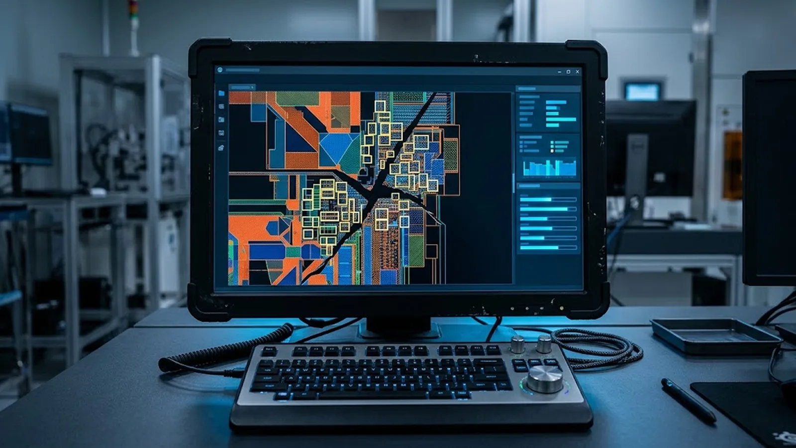
A defensible strategy evaluation reduces to counting. For each representative layout, compute the written area fraction, the number of distinct figures, and—after fracturing under each candidate strategy—the number of exposure shots with their dwell times. Multiply shots by dwell plus move-settle time, add stage moves between subfields and fields, and the result is a writing time with visible assumptions. Run this for the layouts you actually ship: the dense grating that raster covers efficiently, the sparse device layer that vector finishes in a fraction of the sweep time, the repetitive array where cell projection multiplies throughput. The comparison is numerical, auditable, and independent of marketing vocabulary.
Then check the second-order consequences before committing. High shot counts at small dwell interact with dose statistics and line-edge roughness; dense adjacent exposures interact with proximity effects and the dose modulation that corrects them, following the methods in the [proximity effect correction guide](/technology/electron-beam-lithography-proximity-effect-correction-guide/). Whatever the strategy, resist and process decisions set the dose that all of this spends, so the writing-strategy choice belongs inside the same process review rather than beside it. Teams that keep a small set of benchmark layouts, re-counted whenever the product mix shifts, hold their throughput commitments against real evidence instead of the machine class on the order confirmation.
CONCLUSION
Raster, vector, shaped beam, and cell projection are not rankings but different contracts between pattern content and beam time. Raster promises predictable time per field and rewards dense coverage; vector spends flashes only on written geometry and rewards sparse layouts until figure count overwhelms them; shaped-beam and cell-projection architectures multiply pixels per flash and reward patterns their rectangles and cells can represent. A wrong choice here is not a small inefficiency—it can be the difference between an overnight write and a lost week, or between stable linewidths and dose statistics pushed past their useful regime.
The working evaluation is compact and numerical: extract pattern statistics, fracture representative layouts under each candidate strategy, count shots and dwell times, add settling and stage moves, and check the result against dose and roughness requirements. Strategy is fixed in hardware, but which hardware is right is decided by the layouts you write—so make the layouts, not the brochure, the arbiter.
SOLUTION ROUTES
EVIDENCE CHECKLIST
FAQ
No. Vector scanning skips empty space, so it wins on sparse layouts. On dense, nearly full-field patterns, raster's fixed sweep uses beam time efficiently and can match or beat a vector system that pays move-settle overhead on every one of millions of figures. The crossover depends on coverage and figure count, which is why both should be counted for representative layouts.
A variable-shaped beam exposes a flashable rectangle of adjustable size instead of a single spot, delivering many pixels per flash. It is worth the substantially higher machine cost when layouts are large, dense, and dominated by rectangular geometry—typical of industrial lithography and mask writing. Curvilinear or highly irregular geometries fracture into many small rectangles, eroding the advantage.
Indirectly but significantly, through dose statistics per shot. Strategies that slice a pattern into many small flashes with short dwell times reduce the number of electrons per shot, and when that approaches the shot-noise limit, roughness grows at fixed dose. Coarser shots, higher beam current, or a shaped-beam architecture restore margin; the trade should be checked against the roughness budget, not assumed away.
The strategy is a property of the machine architecture, but its parameters—shot organization, fracturing, field and subfield sizes, dose modulation—are data-preparation settings. The same layout written on the same machine can vary greatly in time and fidelity depending on these settings, so strategy-level tuning happens in the data path even when the hardware is fixed.
At minimum: the representative layout or layout class used, shot count after fracturing, beam current and dwell assumptions, deflection settling model, stage-move assumptions, and the resist dose. A quotation without these cannot be compared across strategies or re-verified when your patterns change.
AUTHORITATIVE SOURCES
TECHNICAL REVIEW
Send the application, critical parameters and any drawing or process information available.
Discuss your application ↗