
Undercut or outward-sloping sidewalls
The developed resist profile must open toward the substrate—an undercut or a controlled slope—so deposited metal separates cleanly at the resist edge instead of forming a continuous coating.
TECHNOLOGY / METAL PATTERNING WORKFLOWS
Lift-off replaces etching as the metal patterning route whenever the substrate cannot tolerate an etchant—but its success is decided in the lithography step, before any metal is deposited. This guide walks through resist selection, dose and development for the required sidewall profile, deposition geometry and the failure modes that appear between the resist image and the finished metal film.
Published
DIRECT ANSWER
Lift-off patterns metal by depositing it over a patterned resist layer and dissolving the resist underneath, so the metal above the resist lifts away and only the metal that reached the substrate remains. It is the patterning route of choice for metals that are difficult to etch, substrates damaged by etchants, and work flows that frequently change geometry—because the patterning definition happens entirely in the resist image and the deposition, with no etch chemistry to develop.
The process works when the resist profile is undercut or reentrant: the sidewalls slope outward toward the substrate so the deposited film breaks cleanly at the resist edge, leaving a discontinuity that the solvent can attack. In maskless direct-write lithography, that sidewall shape is controlled through dose, resist choice and development—the DMD grayscale capability can deliberately bias the exposure profile at feature edges to generate a controlled undercut without a bilayer stack. The quality of that profile, plus deposition geometry and resist removal technique, determines whether the result is clean metal lines or fencing, residue and lifted edges.
ENGINEERING CONTEXT
Metal patterning looks like a deposition problem and is actually a lithography problem. An engineer receives a device that needs interdigitated electrodes on glass, or gold interconnects on a piezo substrate that every wet etchant attacks, and reaches for lift-off—then finds the result riddled with the classic signatures: metal fences along line edges, 'ears' of lifted material standing proud of the film, ragged linewidths, and residue that survives the solvent bath. The root cause is almost always upstream: the resist sidewall was vertical or reentrant, so the deposited film was continuous over the edge and never separated cleanly; or the dose window drifted and the developed image no longer had the undercut the process assumed. Maskless direct write changes the degrees of freedom—dose, edge bias, development conditions can all be tuned per design revision, quickly—but it also removes the fixed mask as an excuse, meaning the resist profile is now a deliberately chosen variable that has to be engineered and verified, not inherited from a mask process that worked once.
Discuss your requirement ↗CRITICAL REQUIREMENTS
The developed resist profile must open toward the substrate—an undercut or a controlled slope—so deposited metal separates cleanly at the resist edge instead of forming a continuous coating.
In direct-write lithography the sidewall shape is set by dose distribution and development; the process must define, document and periodically re-verify the dose bias and development conditions that produce the required profile.
Evaporation or sputter incidence angle, target thickness and rotation must respect the resist profile—thick films on steep undercut walls close the opening and destroy lift-off.
The removal step must dissolve and lift metal-supported resist without mechanical or ultrasonic shock that tears line edges, and must leave no residue on the patterned metal or substrate.
BUYER MATRIX
Give every shortlisted supplier the same process definition and request configuration-specific proof.
| Aspect | Lift-off | Wet etching | Ion etching (milling) |
|---|---|---|---|
| Resist profile requirement | Undercut or sloped sidewalls—profile defines the process | Vertical walls; profile matters less | Vertical walls; erosion of the mask matters |
| Substrate compatibility | Etchant-free—suits piezo, polymer and fragile substrates | Requires an etchant safe for the substrate and adjacent films | Universal but energetic; heating and redeposition effects |
| Edge definition and minimum feature | Edges inherit the resist image; fencing risk if profile is wrong | Isotropic undercut widens features; edge chemistry-dependent | Anisotropic and precise; mask erosion sets the limit |
| Metal compatibility | Any depositable metal or stack, including hard-to-etch adhesion stacks | Requires selective etch chemistry per metal | Universal, with rate control per material |
| Design iteration cost | High with direct write—resist and dose changes only | New mask or etch qualification per geometry change | Similar mask dependency |
Lift-off works on a simple geometric condition: the metal film deposited over the resist must be discontinuous at the resist edge. When the sidewall slopes outward toward the substrate—an undercut profile—vapor or sputtered material lands on the resist top and the substrate floor but the sidewall shadow leaves a gap at the base of the step. The film above and the film below are separate, the solvent reaches the resist, and the top metal lifts as a coherent sheet. When the sidewall is vertical or reentrant, the deposited film runs continuously up the wall and over the top; the solvent cannot reach the resist beneath a continuous metal coating, and lift-off degrades into tearing, fencing and partial removal.
That condition makes the lithography step the process's foundation. A conventional mask process inherits its profile from a resist system chosen once; a maskless direct-write process owns the profile as a tunable variable. Dose controls the developed image's width and wall shape directly—slight overexposure at the feature edge can deliberately relax the sidewall slope—and DMD-based systems can apply that bias per edge in the pattern data itself, using grayscale or feature-level dose adjustment to generate the undercut without a bilayer resist stack. Multilayer approaches with an undercutting lower layer remain the robust fallback for thick films or very small features, but direct write often reaches the required profile in a single resist with the right dose strategy.
Verification is non-negotiable because the profile is invisible in the final result—only its consequences are. A cleaved or focus-milled cross-section of the developed resist, inspected before the first deposition of any new design, is the evidence that separates a process from a habit.
Resist selection starts with the metal thickness to be lifted, not the lithographic feature size. A common working rule keeps resist thickness at least twice the metal film thickness, because the deposition must not fill the resist opening toward the top—or the film bridges and the lift-off fails at the center of features, not just at edges. For thick metal, thicker resist or a high-aspect-ratio-capable resist system is required, and the exposure strategy must hold sidewall quality across the full depth.
Dose is the direct-write lever for the sidewall. A dose matrix on the actual substrate and resist—stepped from underexposure through overexposure—shows where the developed image narrows, where the wall gains the desired outward slope, and where the image swells or scums. The chosen dose is a point in that matrix with margin, and because maskless systems dose-calibrate their exposure field, the profile survives between sessions the way a mask process's does only if the dose reference is maintained.
Development completes the profile. Underdevelopment leaves scum and steep walls; overdevelopment erodes the base and widens features while improving the undercut. A descum step after development—brief, mild oxygen plasma—clears residual scum from the substrate floor and is often the difference between clean adhesion and peeling metal. The developer temperature, agitation and time belong in the process record alongside dose, because the profile is their joint product.
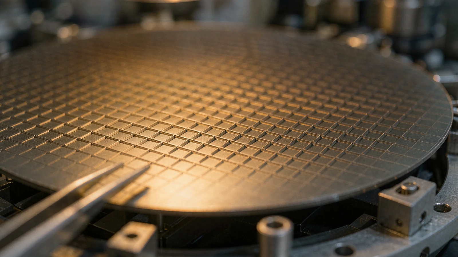
Evaporation at normal incidence is the most lift-off-friendly deposition: the sidewall shadow preserves the discontinuity, and the film thickness is uniform across features of modest aspect ratio. Sputter deposition, with its broad angular distribution, coats sidewalls aggressively; on tight profiles it closes the gap at the resist base and compromises lift-off, so sputtered lift-off processes usually run gentler profiles, thinner films, or accept edge treatment afterward. Rotation during evaporation trades sidewall shadowing for coverage uniformity—the trade must be evaluated against the specific profile, not decided in the abstract.
The signature failures map directly to their causes. Fencing—a thin wall of metal standing along line edges—comes from metal deposited onto the resist sidewall that stayed behind after lift-off; it shrinks with a better undercut and cleaner removal. Ears or crowns of metal at feature perimeters come from the film step coverage over a near-vertical wall. Ragged edges trace back to the developed image, not the deposition: a noisy or scumming development shows up verbatim in the metal. Peeling or lifted patterned metal is adhesion—skipped descum, contaminated substrate, or an adhesion layer chosen for the deposition system rather than the device.
Metal stacks need the same attention as profiles. Adhesion layers—titanium, chromium, thin nichrome—change stress and edge behavior of the stack, and their own etch or lift behavior matters if the patterned device later sees further processing. A lift-off process is a stack process; record it as one.
Removal starts with the gentlest effective solvent at room temperature and time—soaking until the resist dissolves and the overlying metal sheet floats free—before any agitation. Ultrasonic baths remove stubborn residue and also rip fragile metal edges off the substrate; on fine electrodes they are a last resort at low power, not a default. Heated solvent baths and dedicated remover chemistries clear crosslinked resist, and a final oxygen plasma descum polishes residue from the substrate floor—after confirming the plasma will not attack the deposited metal or alter its surface.
Inspection closes the loop on three levels: the metal pattern's linewidth and edge quality against the design, the presence of fencing, ears and residue against the criteria sheet, and the functional parameters—sheet resistance, electrode geometry, optical scattering—against the device requirement. Every observed defect has an upstream owner: profile, dose, development, deposition or removal. A process record that keeps those five fields per run turns inspection results into process learning rather than anecdotes.
This is where maskless direct write compounds its advantage. Each design revision changes only pattern data and, if needed, dose—no mask, no etch requalification. An electrode geometry iterated five times in a week on the same resist and deposition recipe is a routine direct-write workflow, and the lift-off process around it holds still while the design moves.
CONCLUSION
Lift-off succeeds or fails on the resist profile: an undercut or outward-sloped sidewall, held consistently across the exposure field, is what lets deposited metal separate cleanly and the solvent do its work. Direct-write lithography makes that profile a controlled variable—through dose, edge bias and development—rather than a property inherited from a fixed mask process.
Specify the profile, verify it in cross-section before the first deposition, respect the deposition geometry it implies, and remove the resist gently. With those disciplines, lift-off delivers clean metal features on substrates no etchant could touch, and the direct-write workflow iterates the geometry as fast as the design changes.
EVIDENCE CHECKLIST
FAQ
Fencing is metal deposited on the resist sidewall that remained after development. It indicates the sidewall was too vertical—the deposited film was continuous or near-continuous over the edge. Increase the undercut through dose bias at feature edges, adjust development, or use a bilayer resist; a descum before deposition also improves edge cleanliness.
It can, with care. Sputter deposition's wide angular distribution coats sidewalls and can bridge the resist opening, so sputtered lift-off processes typically use thicker undercut profiles, thinner films, or collimation. Evaporation at near-normal incidence is the more forgiving choice for standard lift-off.
A practical starting rule is resist thickness at least twice the metal thickness, so the deposition does not fill the resist opening. For thicker metal, use thicker or high-aspect-ratio resist systems, and verify that the sidewall profile survives the exposure and development at full depth.
Adhesion failure, most often from residual scum or contamination on the substrate floor before deposition. A descum plasma step after development, clean substrate handling, and an appropriate adhesion layer in the metal stack address the common causes.
The fundamentals are identical, but direct write gives you control of the sidewall profile through dose distribution—including per-edge bias in the pattern data—so the undercut can be engineered in a single resist without a separate mask revision. The profile still needs the same cross-section verification and dose documentation.
AUTHORITATIVE SOURCES
TECHNICAL REVIEW
Send the application, critical parameters and any drawing or process information available.
Discuss your application ↗