
Controlled thermal uniformity
Hotplate and chill plate temperature uniformity, ramp rates and setpoint stability specified and verified across the substrate area, with the substrate temperature—not just the plate—considered.
TECHNOLOGY / LITHOGRAPHY PROCESS
Between exposure and development, resist bakes can move the substrate more than the overlay budget allows. This guide explains how soft bake, post-exposure bake and chill steps distort substrates, how those distortions interact with encoder-based stage metrology in maskless lithography, and how to control bake-induced overlay error.
Published
DIRECT ANSWER
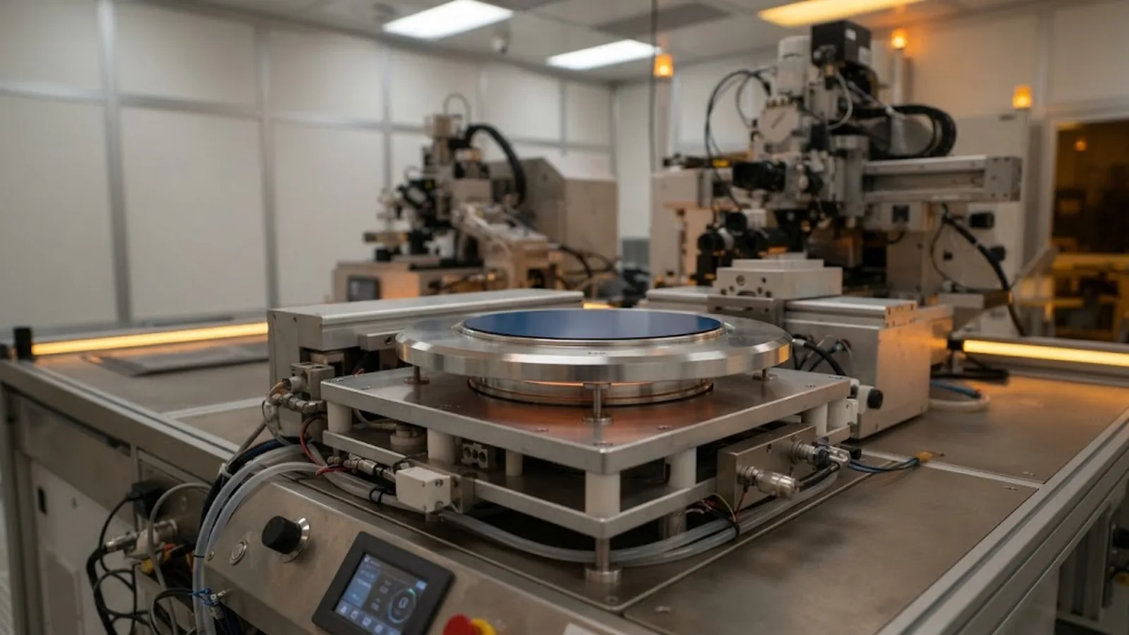
Resist bake steps deform the substrate, and that deformation becomes overlay error. Soft bake, post-exposure bake (PEB) and chill steps each impose temperature gradients and film stress changes that bow or warp the substrate; when the substrate is removed from the chuck, cooled, and returned for a subsequent layer, its shape and its pattern placement differ from the previous pass. Typical bake-induced shifts range from tens of nanometres on rigid, thick substrates to micrometres on thin or stressed stacks—enough to consume an entire overlay budget in precision maskless lithography.
Control comes from treating bake as a metrology step, not just a process step. Bake on the same chuck geometry used for exposure where possible, control hotplate and chill plate temperature uniformity and transfer time, keep bake parameters fixed once overlay is qualified, and measure the distortion directly—alignment marks read before and after bake, or overlay metrology on dedicated test patterns—so the contribution is quantified and can be assigned within the overlay error budget rather than blamed on the tool.
ENGINEERING CONTEXT
In a maskless lithography workflow, overlay is measured and tuned at the exposure tool: encoder-feedback stage accuracy, alignment marks, autofocus. Yet a common failure mode appears after the wafer has left the tool—bake the resist, develop, come back for the next layer, and overlay has degraded even though the tool reports perfect stage repeatability. The distortion happened between exposures, on a hotplate. Film stress changes during soft bake, anisotropic temperature gradients during PEB, and nonuniform cooling on the chill plate each reshape the substrate, and no amount of stage accuracy can compensate for a substrate that no longer sits where its previous pattern did. Teams that lack a bake-side overlay budget end up chasing a phantom tool problem.
Discuss your requirement ↗CRITICAL REQUIREMENTS
Hotplate and chill plate temperature uniformity, ramp rates and setpoint stability specified and verified across the substrate area, with the substrate temperature—not just the plate—considered.
Identical transfer times, lift-pin vs vacuum contact behavior and cooling geometry for every wafer, because transient gradients during transfer cause as much distortion as the bake itself.
Bake temperature, time and recipe changes treated as overlay-relevant events requiring requalification, since distortion scales with recipe.
Alignment mark or overlay metrology before and after bake on a representative substrate, feeding a quantified bake term into the overall overlay error budget.
BUYER MATRIX
Give every shortlisted supplier the same process definition and request configuration-specific proof.
| Step | Primary distortion mechanism | Typical overlay impact | Main controls |
|---|---|---|---|
| Soft bake / pre-exposure bake | Solvent loss and film stress relaxation bowing the substrate | Low to moderate; sets the starting shape before exposure | Uniform plate, consistent time, full edge bead management |
| Exposure-side chucking | Chuck vacuum and flatness imposing local shape during pattern writing | Tool-managed; matters for layer-to-layer correlation | Chuck flatness verification, consistent vacuum pattern |
| Post-exposure bake (PEB) | Temperature gradients through film and substrate; chemically amplified resist redistribution | Highest; can reach micrometres on thin substrates | Plate uniformity, proximity cup, fixed transfer time, controlled ramp |
| Chill plate | Nonuniform cooling rates, edge-first solidification | Moderate; mirrors and can partially cancel or double PEB gradients | Uniform backside contact, defined dwell, clean plate surface |
| Develop and rinse | Swelling and surface tension on fine features | Low for overlay; relevant to CD control | Fixed develop chemistry, time and agitation |
| Hard bake / cure | Further film stress change and substrate relaxation | Moderate; permanent pattern displacement | Ramp control, symmetric loading, requalified recipe |
Every bake is a thermo-mechanical event. The substrate expands with temperature; the resist film and any underlayers expand at different rates and change stress as solvents leave or the resist chemically reacts. The result is bending and in-plane distortion that is rarely symmetric, because heating is rarely symmetric: edge heating, backside contact quality and lift-pin transfer all create gradients. When the substrate returns to room temperature on the exposure chuck, its pattern grid has shifted—usually by a combination of uniform scale change, bow-induced apparent distortion and local warp.
For a single exposure layer, none of this matters. Overlay is where it bites: layer two must land on layer one, and everything that moved the substrate between the two exposures enters the overlay error. In maskless lithography for photonics, MEMS and multi-level devices, overlay budgets of 100 to 300 nanometres are common, while an uncontrolled PEB on a thin glass substrate can shift patterns by more than a micrometre. The tool's encoder-based stage metrology is accurate; the substrate simply is not where the stage's map says it should be.
Post-exposure bake dominates because it is the hottest, longest step and, for chemically amplified resists, functionally critical. Distortion during PEB comes from through-thickness and in-plane temperature gradients: the substrate edge heats faster than the centre when backside contact is poor, and lift-pin transfer adds a transient shock. Two wafers baked with identical setpoints but different transfer times can show measurably different distortion, which is why recipe control must extend beyond the plate to the handling.
The chill step is not neutral either. Rapid, nonuniform cooling freezes in the gradient the substrate had at the end of PEB, and edge-first cooling can bow the wafer in the opposite sense. A chill plate with worn vacuum grooves or contamination under one corner produces a distortion signature that repeats per plate but varies between plates—one of the more confusing overlay failure modes, since 'the recipe did not change' while the hardware did.

The distortion is measurable with modest effort. Read alignment marks or dedicated overlay patterns on a representative substrate immediately after exposure, then again after the complete bake chain, using the same setup and the same metrology. The displacement field between the two readings is the bake contribution: decompose it into translation, scale, rotation and residuals. A dominated single term points at a specific cause—pure scale change suggests uniform temperature error, edge-heavy residuals suggest plate nonuniformity or transfer asymmetry.
Once quantified, the term earns its place in the overlay error budget alongside stage accuracy, alignment error and pattern-placement contributions. Two practical cautions: measure on the production substrate stack, because distortion scales with substrate stiffness and film stress, not on a convenient dummy; and re-measure after any recipe, plate or resist change, because the term does not transfer between them.
Where the process allows, the strongest control is architectural: bake on the same chuck geometry used for exposure, or perform exposure and development between bakes without re-clamping, so distortion never has a chance to accumulate between pattern layers. Where separate plates are unavoidable, choose proximity-style uniform heating, verify plate maps periodically, fix handling, and keep a log linking every overlay campaign to its exact bake recipe and hardware.
With those disciplines, bake distortion becomes a stable, quantified, partly compensable term rather than a random one. Some of it can even be pre-compensated: if the distortion field is repeatable, the maskless data path can apply a distortion correction to later layers, provided the compensation is requalified whenever the bake chain changes. The guiding principle is the same as anywhere in precision work—an error you can measure and hold constant is an error you can manage.
CONCLUSION
Encoder-feedback stage accuracy and alignment performance define what a maskless lithography tool can deliver at the moment of exposure. What actually lands on the wafer also depends on everything that happens to the substrate in between—soft bake, PEB, chill and cure each reshape it, and those reshapes are the overlay error no stage can correct.
Treat the bake chain as part of the metrology: uniform and verified plates, fixed handling, measured distortion on production-representative stacks, and an explicit bake term in the overlay budget. With the contribution quantified and held constant, multi-layer maskless lithography reaches overlay performance that the tool-side numbers alone would promise and the process would otherwise quietly destroy.
EVIDENCE CHECKLIST
FAQ
It depends mainly on substrate stiffness and film stack. Rigid, thick substrates often show tens of nanometres; thin glass, membrane or highly stressed film stacks can see shifts of several hundred nanometres to more than a micrometre after PEB. The only reliable number is a measurement on your own stack, taken before and after the bake chain.
Usually the post-exposure bake, because it is the hottest and longest step and involves the largest stress and gradient changes. The chill step follows closely, since nonuniform cooling freezes in whatever gradient PEB created. Soft bake matters mainly by setting the substrate shape before exposure.
Distortion depends on hardware condition and handling, not only on setpoints. Chill plate contamination, worn vacuum grooves, changed lift-pin timing or a different loading pattern can alter gradients while the recipe stays identical. Plate condition belongs in preventive maintenance with overlay-relevant checks.
Partially, when it is repeatable. Measuring the distortion field between exposure and post-bake lets later layers be written with a pre-applied correction. This works only while the substrate stack, bake recipe and hardware stay fixed, so any change requires requalification of the compensation.
Alignment mark quality and reading error, pattern placement from data preparation, bake-induced substrate distortion, chucking repeatability and metrology uncertainty. A budget that credits the stage's full accuracy to the process leaves no room for these terms and predicts better overlay than the flow can deliver.
The substrate and film stack, the resist and bake recipe, the overlay target between layers and any existing overlay measurements. SENFU can help attribute error terms across tool and process and define the measurements needed to qualify the bake contribution.
AUTHORITATIVE SOURCES
TECHNICAL REVIEW
Send the application, critical parameters and any drawing or process information available.
Discuss your application ↗