Maskless Lithography Substrate Chuck Flatness, Focus Control and Depth-of-Focus Budget: What Buyers Should Verify
Linewidth uniformity in maskless and direct-write lithography is usually limited by substrate height variation, not by the imaging system. This guide explains how vacuum chuck flatness, wafer and substrate bow, clamping deformation and autofocus strategy together consume the depth-of-focus budget, how to build that budget before a purchase, and which acceptance measurements belong in a system qualification.
Published
DIRECT ANSWER
What should a buyer prioritize?
In a direct-write system there is no mask to average out substrate topography, so every micrometre of height variation across the substrate is translated directly into focus error and then into linewidth variation. The practical limit is set by the depth of focus of the imaging optics, and the budget that matters is the sum of substrate bow, chuck flatness, clamping deformation, chuck-to-stage mounting error and residual autofocus error compared against that depth of focus.
For an acceptance test, require three things: a documented substrate flatness specification stated as a range over a defined area with the measurement instrument and conditions named; a depth-of-focus statement for the objective and feature size used in your process; and a demonstrated linewidth uniformity result across the full substrate, measured with your substrate type, thickness and resist stack. A patterned result over the full usable area is the only evidence that closes the loop, because flatness numbers alone do not prove that the focus system compensates the real substrate.
ENGINEERING CONTEXT
The decision starts with the real constraint.
Buyers compare lithography systems on headline resolution, and then find that linewidth uniformity across a 4-inch or 8-inch substrate is limited by something the specification sheet never mentions: how flat the substrate sits, and how well the focus system tracks whatever shape it has. Vacuum clamping pulls a bowed wafer towards the chuck, but not perfectly and not uniformly; the chuck itself has form error and mounting-induced distortion; the substrate arrives with its own bow, warp and thickness variation; and the autofocus loop has a finite bandwidth, a finite sampling strategy and its own offset. Each term is small, and together they routinely consume most of a high-numerical-aperture objective's depth of focus. The consequence is a process that resolves test features beautifully in the centre of the field and drifts out of specification towards the edge, which is exactly where production dies and devices are lost.
Measure bow, warp, total thickness variation and site flatness of the actual substrate material and thickness used in production, with the measurement instrument and reference plane stated. Incoming substrate quality sets the floor for everything else.
02
Specify chuck flatness with conditions
Require chuck flatness stated as peak-to-valley and, preferably, as a height map over the defined clamping area, under vacuum, at a stated temperature, with the measurement method named. A number without those conditions is not comparable between suppliers.
03
Build an explicit depth-of-focus budget
Sum every height contributor and compare it with the depth of focus of the objective and feature size used in your process, with margin. This is the calculation that decides whether a given resolution claim is achievable across the full substrate.
04
Verify with patterned results, not specifications
Acceptance should include linewidth or critical-dimension uniformity measured across the full usable substrate area, using your resist stack, dose and development conditions, with the measurement locations and statistics defined.
BUYER MATRIX
Compare evidence, not feature labels.
Give every shortlisted supplier the same process definition and request configuration-specific proof.
Contributors to the vertical error budget in a direct-write lithography system and how each one is controlled
Height contributor
Typical origin
How it is measured
Primary control
Substrate bow and warp
Wafer or panel manufacturing, film stress from previously deposited layers, thickness and material
Capacitive or optical flatness measurement of the substrate as received, stated over a defined site size
Incoming substrate specification and sorting; process-side film stress control
Substrate thickness variation
Wafer grinding, polishing, or bonded and laminated substrates
Thickness mapping across the substrate, reported as total thickness variation
Substrate specification; thickness compensation in the focus system where offered
Chuck form error
Machining, lapping or grinding of the chuck surface, and long-term wear or damage
Interferometric or profilometer measurement of the chuck surface under vacuum, reported as peak-to-valley over the clamping area
Chuck manufacturing specification and periodic re-qualification; careful handling to avoid damage
Vacuum clamping deformation
Elastic deformation of the substrate pulled towards the chuck, contact at asperities, incomplete conformity where bow exceeds chuck conformity
Height mapping with vacuum applied compared against the unclamped substrate shape
Chuck design: groove layout, vacuum level, contact surface finish, and staged or zone-controlled clamping
Chuck mounting and stage error
Bolted or kinematic mounting distortion, thermal expansion mismatch, stage straightness and flatness of travel
Height mapping of the chuck mounted on the stage, and stage flatness measured over the full travel
Mounting design with defined torque and thermal symmetry; stage flatness specification
Autofocus residual error
Sensor offset from the exposure plane, sampling density between focus points, loop bandwidth relative to stage speed, sensor noise
Residual focus error logged during a full-substrate exposure, compared against the commanded surface
Sensor calibration, focus sampling strategy, and sufficient focus update rate at the writing speed used
Thermal drift
Stage and chuck expansion during a long write, resist heating, ambient drift in the enclosure
Height or focus log over the duration of a full write
Thermal stabilisation, warm-up procedure, and drift compensation between focus passes
An optical direct-write system images a pattern onto a resist-coated surface through an objective with a finite depth of focus. Within that depth the image stays acceptably sharp; beyond it the aerial image broadens, contrast falls and the developed linewidth changes. Depth of focus decreases as numerical aperture increases and as the target feature size shrinks, so the systems bought for the finest features have the least tolerance for substrate height variation. That is the central tension in direct-write lithography.
A mask aligner or stepper benefits from a mask that is flat by construction and from a projection system that averages over the exposure field in a different way. A direct-write system has no such averaging: it writes pixel by pixel or field by field across whatever surface is there, so the substrate height profile appears directly in the focus history. Height variation also modulates dose, because the effective dose at the resist changes as well as image sharpness, and linewidth responds to both.
The practical implication for a buyer is that a resolution number demonstrated on a flat coupon in the centre of the field does not predict uniformity across a bowed substrate. The right question is not what the system resolves, but what it holds across the full substrate under the real clamping and focus strategy.
Chuck flatness, clamping deformation and what a specification should say
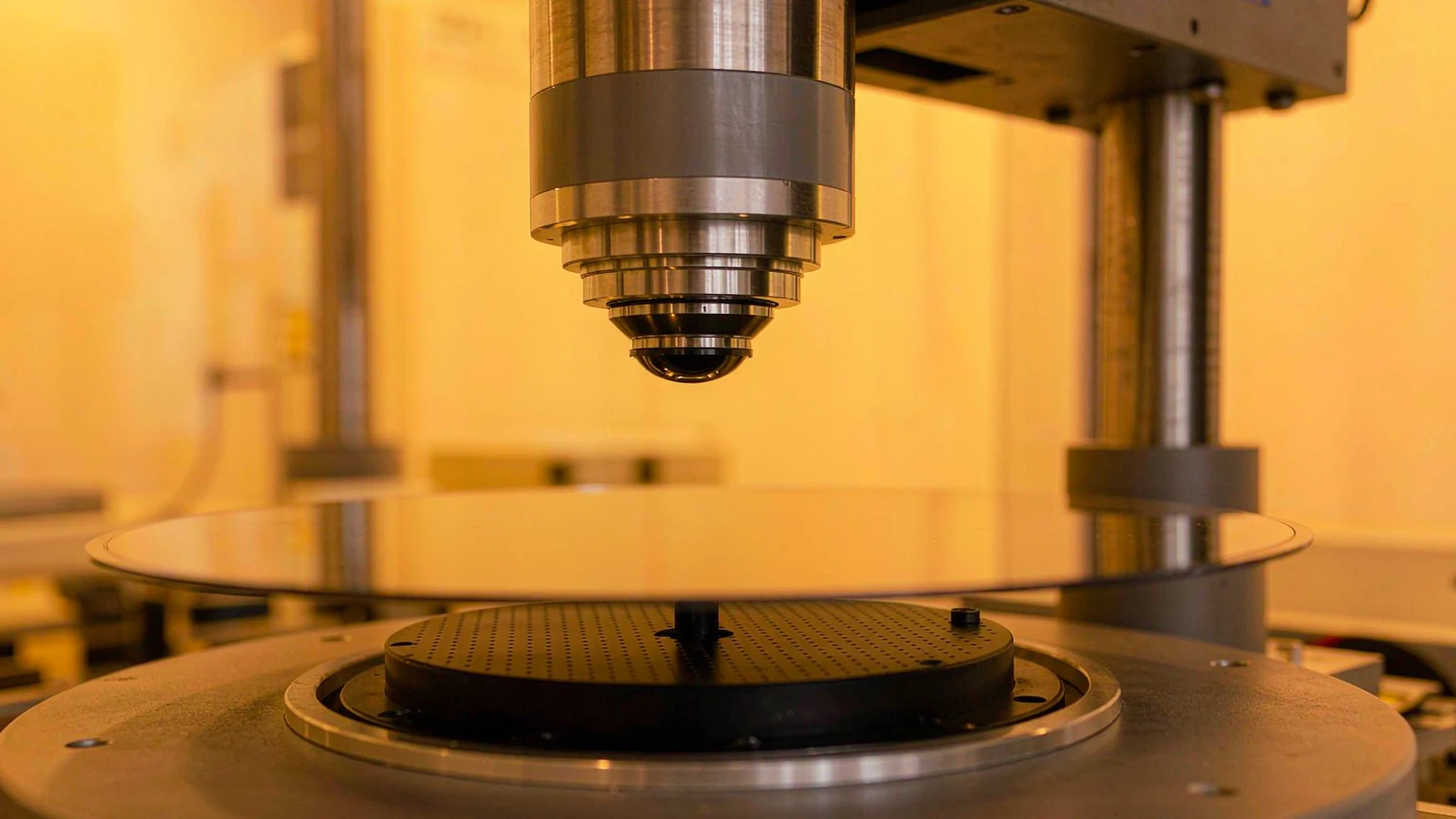
A vacuum chuck holds a substrate by pressure differential, and that same mechanism deforms it: the substrate is pulled towards the chuck and conforms to the extent that its stiffness and initial shape allow. A thin, compliant substrate conforms well and inherits the chuck form error; a thick, stiff or bowed substrate conforms only partially, leaving a residual shape the focus system must track. Both fail differently, which is why one flatness number cannot answer a buyer's question.
The chuck surface contributes form error from manufacturing, and more once it is mounted: a chuck lapped flat on a bench is not necessarily flat after it is bolted to a stage at defined torque, because the mounting interface transmits stress into the chuck body. Thermal mismatch adds a further term when chuck, stage and substrate expand at different rates during a long write. A complete specification therefore separates chuck form error from mounted flatness and states both under vacuum at a defined temperature.
Groove layout and vacuum level matter more than they appear to. Grooves define where the substrate is supported and where it is free to sag; too aggressive a vacuum can increase local deformation near the grooves and distort thin substrates at the perimeter. A specification naming the groove pattern, vacuum level and contact geometry gives a process engineer something to reason about; one that says only 'flat to within a few micrometres' does not.
How to specify chuck flatness in a purchase document
Ask for these items explicitly so that quoted numbers are comparable between suppliers:
Flatness stated as peak-to-valley and as a height map over the defined clamping area, not a single scalar
Measurement condition: vacuum applied, chuck mounted on the stage, stated temperature and warm-up state
Measurement instrument and method named, with stated uncertainty
Separation of chuck form error from mounted flatness and from substrate conformity
Groove pattern, vacuum level and staged or zoned clamping options where relevant
Re-qualification interval and the handling or damage procedure for the chuck surface
The budget is a single comparison: total vertical variation versus available depth of focus, with margin. Build the numerator from the substrate as received, the chuck under vacuum, the mounting and stage error, the residual clamping deformation and the autofocus residual. Build the denominator from the objective numerical aperture, wavelength and the feature size you need, using the supplier's depth-of-focus data for that configuration rather than a textbook approximation. Then require the numerator to stay inside the denominator with margin for drift over a long write.
Two moves change the budget more than any other. The first is substrate selection: tighter bow, warp and total thickness variation on incoming substrates removes a large term at low cost. The second is the focus strategy. A system that samples the surface over a grid and interpolates handles smoothly varying bow well; one that tracks continuously handles local variation better; one that only levels the substrate handles neither well. The choice follows the shape of your substrate, which is why measuring it before purchase is the highest-value preparation.
Ask also what happens at the edge of the usable area, where budgets fail: edge clamping geometry, chuck edge form, substrate edge exclusion and the focus system's behaviour at the boundary of its mapped region all combine. Require uniformity data covering the outer region, not only a central array of sites.
Autofocus systems differ in sensor principle, in where the sensor measures relative to the exposure plane, and in how focus updates are distributed during a write. The offset between the sensor measurement point and the exposure plane is a calibration quantity and must be stable: drift in that offset is a systematic focus error on every substrate written. Sampling density matters when the substrate shape varies faster than the sample spacing, and update rate matters when the stage travels far between updates. The relevant question is what residual focus error the system achieves at your writing speed and pattern density.
There is also a distinction between tracking a real surface and trusting a model. A mapped approach measures once and follows the map; a continuous approach measures as it writes. The former is efficient and suits stable substrates but does not correct drift unless re-measured. The latter is robust to drift but costs time or hardware. Ask which strategy is used, whether both are available, and the residual for each under a representative write.
Verification should be empirical. Require the system to log focus error during a full-substrate exposure and report the statistics. Then correlate that log with a linewidth map over the same substrate: if linewidth variation tracks the focus residual, the budget model is confirmed and improvement should come from reducing height variation; if it does not, the limiting term is elsewhere, most likely dose, resist or development uniformity.
Acceptance criteria worth writing into a purchase agreement
Specifications are easier to compare than results, but results are what protect a buyer. Write acceptance around a demonstration: the system must pattern a defined test layout on the buyer's substrate type, thickness and resist stack, and the measured linewidth must stay within a stated range across defined measurement locations including the edge region. Name the instrument, site count and statistics. That single clause converts flatness, focus and dose claims into one observable outcome.
Add the supporting measurements that make the demonstration diagnosable if it fails: substrate flatness as received, chuck height map under vacuum and mounted, focus residual log, and stage flatness and straightness over the travel used. With those, a marginal result can be attributed to a specific term instead of triggering a debate about whether the substrate or the system was at fault. Repeat the demonstration for the largest and most bowed substrate, because those cases expose the budget.
SENFU supports this form of qualification with substrate and process trials on ZML series maskless lithography systems, including flatness and focus data for the intended substrate, active autofocus evaluation where the process benefits, and linewidth uniformity measured over the full usable area. Send the substrate material, size, thickness and flatness data, the resist stack and the target feature size, and the trial can be scoped around those inputs.
Buy the uniformity result, not the flatness number.
Depth of focus is the currency, and substrate bow, chuck form error, clamping deformation, mounting error and autofocus residual all spend it. A high-resolution objective leaves less of it, which is why systems bought for the finest features are the least forgiving of substrate topography. The budget should be calculated before purchase, with the substrate measured rather than assumed.
The acceptance clause that protects a buyer is a patterned uniformity result: a defined layout on the real substrate and resist, measured across the full usable area including the edge region, with the supporting flatness and focus logs that make a marginal result diagnosable. SENFU can scope a ZML series trial around those inputs and report the measurements that decide whether the process window is real.
Substrate flatness as received: bow, warp and total thickness variation with instrument and conditions stated
Chuck height map under vacuum and mounted on the stage, with measurement method and uncertainty
Depth-of-focus statement for the objective and feature size used in the process
Focus residual log from a full-substrate demonstration write at the intended writing speed
Linewidth uniformity measured across the full usable area including the edge region, with site count and statistics defined
FAQ
Questions engineers ask before selection.
Why does linewidth vary across a substrate when the system resolves the target feature?
Because resolution is demonstrated on a flat coupon in ideal focus, while a real substrate has bow, warp and thickness variation that move the surface out of the optimum focus plane. Beyond the depth of focus, image contrast falls and developed linewidth changes even though the imaging system works correctly. Uniformity across the full substrate is a separate specification from resolution at one point.
How flat does a vacuum chuck need to be?
There is no universal number; the requirement follows from the depth of focus of the objective and feature size you use. Add substrate bow, chuck form error, clamping deformation, mounting error and autofocus residual, then require the total to stay inside the available depth of focus with margin. Finer features leave less margin.
Does vacuum clamping flatten a bowed wafer completely?
Only partially. Conformity depends on substrate stiffness, bow magnitude, groove layout and vacuum level. Thin compliant substrates conform closely and inherit the chuck form error; thick or strongly bowed substrates conform incompletely and leave a residual shape the focus system must track. Ask for height mapping with vacuum applied.
What is the difference between surface mapping and continuous autofocus?
A mapped approach measures the surface once and follows the height map, which is efficient and suits stable, smoothly varying substrates but does not correct drift during a long write unless it is re-measured. A continuous approach measures as it writes, handling drift and local variation better but costing time or requiring dedicated hardware.
What should a lithography acceptance test include for flatness and focus?
A patterned uniformity result: a defined test layout on your substrate type, thickness and resist stack, with linewidth measured across the full usable area including the edge region, with instrument, site count and statistics named. Supporting data: substrate flatness as received, chuck height map under vacuum and mounted, and the focus residual log.
How does substrate thickness variation affect the write?
Thickness variation changes the height of the resist surface relative to the chuck reference plane, so it enters the same budget as bow, and on ground, bonded or laminated substrates it can be a dominant term. Measure total thickness variation on incoming material and use thickness compensation or a focus strategy that tracks the resist surface.