
Allocated overlay budget
Require placement, field-matching and layer-to-layer repeatability as separate allocated terms, with the encoder contribution stated rather than hidden inside a total.
TECHNOLOGY / MASKLESS LITHOGRAPHY
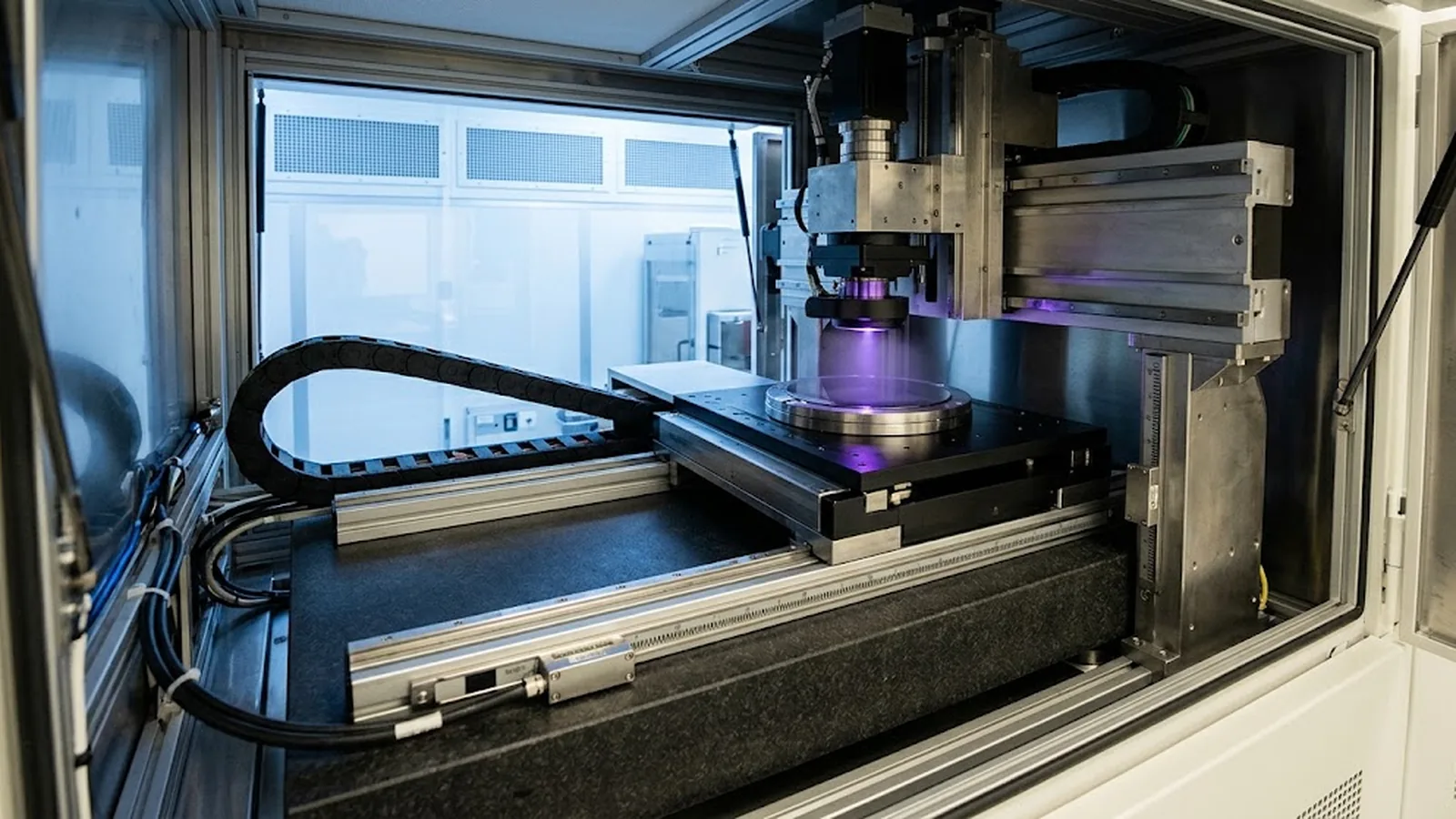
In a maskless lithography tool the stage encoder effectively is the mask: every nanometre of feedback error becomes pattern placement error. This guide decomposes the overlay budget into its encoder-driven terms and shows which measurements and specifications keep multi-layer processes registered.
Published
DIRECT ANSWER
A maskless lithography system has no mask to inherit registration from. The pattern exists only where the writing head is directed, and the stage encoder is the coordinate system the pattern is written into. Every encoder imperfection, scale line error, interpolation noise, Abbé amplification of straightness and yaw, thermal expansion of the scale, and reference repeatability between layer exposures, enters the overlay budget directly, on top of alignment sensing, resist processing and focus contributions.
Control the budget rather than the datasheet. Ask the supplier to allocate overlay into placement, matching and repeatability terms with the encoder contribution quantified at the writing speed used, not only statically. Require an encoder matched to the scale thermal behaviour of the machine, interpolation error and jitter measured in the installed configuration, Abbé arms declared and minimised, and an overlay metrology result across the substrate and between consecutive layers as the acceptance evidence. An encoder that is excellent on paper can still lose overlay if any of those terms is unmeasured.
ENGINEERING CONTEXT
Overlay failures in direct-write tools are seductively easy to blame on resist, focus or alignment marks, because those are the elements the process engineer adjusts daily. The harder truth is that the stage feedback loop sits underneath all of them: a writing beam can only be placed as well as the encoder reports the stage to be, and encoder errors arrive disguised, scale error appears as field distortion, yaw appears as a rotation term that grows with radius, interpolation jitter appears as line-edge roughness, and thermal scale drift appears as a slow shift between the first and last die. None of these show up in a short demonstration at low speed in the middle of the substrate. The buyer who does not force the encoder contribution into the open ends up tuning process knobs against a metrology problem. The remedy is an explicit overlay budget with the encoder terms named, measured in the installed configuration at writing speed, and verified by layer-to-layer overlay metrology at acceptance.
Discuss your requirement ↗CRITICAL REQUIREMENTS
Require placement, field-matching and layer-to-layer repeatability as separate allocated terms, with the encoder contribution stated rather than hidden inside a total.
Ask for interpolation error and position jitter measured at the writing velocity and data rates used on-the-fly, not only quasi-static laboratory figures.
Require the Abbé offsets between encoder and substrate plane, the scale material and its thermal expansion behaviour, and how compensation is implemented.
Specify an overlay measurement plan across the substrate area and between consecutive written layers, with the measurement method and sample pattern defined before order.
BUYER MATRIX
Give every shortlisted supplier the same process definition and request configuration-specific proof.
| Encoder mechanism | Physical origin | Overlay symptom | Control to require |
|---|---|---|---|
| Scale line error | Local grating pitch deviations along the scale | Field distortion that repeats at the same stage coordinates on every layer | Scale accuracy grade at operating temperature, optional error mapping compensation |
| Interpolation noise | Signal imperfections amplified by high subdivision factors | Line-edge roughness and jitter that blur small features at speed | Subdivision error measured in the installed configuration at writing velocity |
| Abbé amplification | Straightness and yaw errors multiplied by the offset between encoder and substrate plane | Placement error growing toward substrate edges and varying with part height | Declared and minimised Abbé arms, straightness and yaw specification for the stage |
| Thermal scale drift | Expansion or contraction of the scale with temperature gradients | Slow shift and scaling mismatch between the first and last die of an exposure | Low-expansion scale material matched to the structure, warm-up and gradient limits |
| Reference repeatability | Datum re-acquisition after power cycle or substrate exchange | Layer-to-layer offset that steps rather than drifts, confusing process tuning | Reference-mark strategy with measured repeatability across operating cycles |
| Axis coupling errors | Yaw and orthogonality between the X and Y measurement axes | Rotation and non-orthogonality terms that grow with pattern radius | Two-axis encoder geometry specification and machine calibration records |
A projection lithography tool transfers registration from a physical mask; a maskless tool transfers it from the motion system. The layout file contains ideal coordinates, but the position those coordinates actually land at is the position reported by the stage encoders at the moment of exposure. In that sense the encoder is not merely a servo component but the pattern coordinate system itself. Any error it reports, the writer believes, and the resist records. This is why overlay conversations that treat the encoder as a solved commodity so often end with unexplained placement scatter.
The consequence for procurement is structural: overlay claims must decompose, and the encoder line in the decomposition must carry a number. A single figure for overlay accuracy hides whether the budget is spent on alignment sensing, stage geometry, thermal behaviour or feedback error. Suppliers who allocate the budget are inviting verification; suppliers who do not are asking to be trusted. Since multi-layer processes multiply whichever weakness exists, the allocation matters more in direct write than in any mask-based flow.
A workable budget separates three families of terms. Placement error describes how accurately a feature lands relative to the machine coordinate system within a single field, dominated by scale accuracy, interpolation error and the writer optics. Field matching describes how consistently consecutive fields land relative to each other, dominated by stitching behaviour, reference repeatability and stage dynamics. Layer-to-layer overlay describes how the whole written pattern registers against the previous layer, adding the alignment sensor, substrate handling and process contributions on top.
Encoder feedback appears in all three, but with different faces. In placement it is scale error and interpolation noise. In field matching it is datum repeatability and velocity-dependent feedback lag during settle. In layer-to-layer overlay it is thermal drift and reference strategy, because the second exposure must rediscover the coordinate system the first one used. Asking for the encoder contribution to each family separately is the single most revealing question a buyer can pose, and the hesitation or fluency of the answer is itself evidence.
The mapping from feedback physics to resist image is worth knowing because it makes diagnosis faster. Scale line error repeats at fixed stage coordinates, so the same distortion signature appears in every layer written at the same field, a fingerprint error mapping can compensate. Interpolation noise is random and speed dependent, so it survives into line-edge roughness and vanishes in slow tests. Abbé error multiplies small angular and straightness errors by the distance between the encoder axis and the focal plane, which is why placement degrades toward substrate edges and why tall chucks change results.
Thermal drift is the slowest and most misleading term: a scale warming under motor and encoder electronics heat expands, so features written late in a run sit at slightly stretched coordinates relative to early features. Between layers, the drift becomes an overlay scaling mismatch that process engineers chase through dose and bake. Each of these has a countermeasure, compensation tables, dynamic verification, Abbé arm minimisation, scale material selection and warm-up discipline, but none can be applied to a term that was never measured.
Stop-and-expose writing hides the hardest feedback problem; writing on-the-fly exposes it. When the writer fires while the stage moves, the exposure coordinates are a fusion of encoder position sampled at high rate, writing-clock timing and galvanometer or pixel clock deflection. Encoder data latency, interpolation filter delay and the synchronization scheme between encoder clock and writing clock all become placement errors with the sign of a phase lag: features lead or trail their nominal position by the stage travel during the delay.
Qualifying this regime needs dynamic evidence, not datasheets. Ask for interpolated position error measured in the installed configuration at the actual writing velocity, the latency figure of the encoder data path, and how the writing clock is slaved to position rather than to an independent timebase. A tool that writes only on-the-fly should demonstrate stitching and placement results at speed; a tool that claims both modes should demonstrate both, because the fast mode is usually the one that stresses the encoder chain hardest.
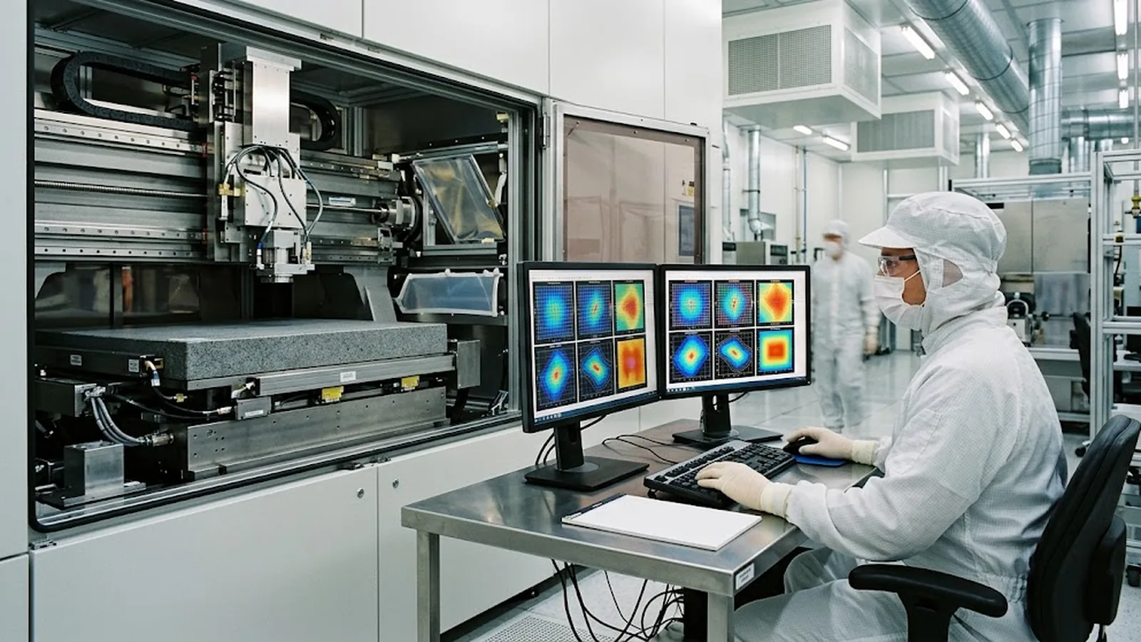
Overlay claims are only as good as the metrology behind them, so the acceptance plan deserves as much attention as the specification. A meaningful plan measures registration across the full substrate area, not only the centre field; measures field-to-field stitching along both axes; and, for multi-layer work, measures actual layer-to-layer overlay using the process engineer's own mark scheme after development. The measurement tool and its uncertainty should be named, because a budget of a hundred nanometres cannot be verified by a microscope reticle.
Structure the results against the allocated budget rather than against hope. Placement residuals that repeat every layer point at machine geometry or scale error; residuals that step between layers point at reference or thermal terms; residuals that correlate with substrate radius point at Abbé or orthogonality. With the allocation in hand, a failing result becomes a diagnosis rather than a dispute, and the corrective action, whether compensation, environmental control or encoder replacement, follows from evidence instead of argument.
Five clauses do most of the work. First, the allocated overlay budget with the encoder contribution stated for placement, field matching and layer-to-layer overlay. Second, dynamic encoder evidence: interpolation error and jitter at writing velocity in the installed configuration. Third, geometry declarations: Abbé offsets per axis, scale material and expansion behaviour, and axis orthogonality. Fourth, reference strategy with measured repeatability across power cycles and substrate exchanges. Fifth, the acceptance overlay metrology plan, defined before order and executed at factory and site acceptance.
The clauses also shape daily operation. Warm-up routines, substrate and chuck temperature stabilisation, and scheduled verification of encoder amplitude and error become budget-maintenance tasks rather than optional hygiene. Tools that treat these as discretionary drift into a state where the original overlay figure is unreproducible, and the process engineer inherits a moving coordinate system. The specification, written once, is what keeps the coordinate system still for the life of the tool.
CONCLUSION
In maskless lithography the encoder feedback defines where the pattern exists, so overlay accuracy is a metrology claim before it is a process outcome. Force the budget to allocate the encoder contribution, verify the dynamic terms at writing speed in the installed configuration, and close the argument with layer-to-layer overlay metrology at acceptance. Tools specified this way keep their registration; tools bought on a single overlay number spend years rediscovering where it went.
EVIDENCE CHECKLIST
FAQ
A mask-based tool inherits registration from the mask pattern itself, while a maskless tool builds the pattern from encoder-reported coordinates in real time. Every feedback error therefore becomes pattern placement error directly.
Not necessarily. Interpolation error grows with signal imperfections and subdivision factor, and dynamic effects such as filter latency appear only at speed. Require the figure measured in the installed configuration at the actual writing velocity.
Abbé amplification is frequently undeclared. Small straightness and yaw errors multiply by the offset between the encoder and the focal plane, producing placement error that grows toward the substrate edges and changes with chuck height.
Scale drift correlates with time into the exposure run and with machine warm-up, appearing as a first-to-last-die scaling shift that repeats across layers and processes. Correlating overlay residuals with run position and stage temperature separates it from dose or bake effects.
A layer-to-layer overlay metrology report across the substrate using your own alignment scheme, plus field-stitching and placement measurements, with the metrology tool and its uncertainty named and the results checked against the allocated budget terms.
AUTHORITATIVE SOURCES
TECHNICAL REVIEW
Send the application, critical parameters and any drawing or process information available.
Discuss your application ↗