
Alignment strategy and mark design
Define the mark type, placement and count for global and field-level alignment, the capture method, and how marks survive each process step including resist coating, development and any etch or bonding.
TECHNOLOGY / MASKLESS LITHOGRAPHY
Overlay in a direct-write tool is a system result, not a single specification. This guide explains the alignment sequence from substrate pre-alignment to field-level mark capture, decomposes the overlay budget into stage, optics, metrology, substrate and thermal terms, shows where encoder feedback enters the result, and sets out a practical acceptance method with sampling, statistics and documented limits.
Published
DIRECT ANSWER
Overlay in maskless lithography is the residual placement error between two patterned layers, and it is the sum of several independent terms: substrate pre-alignment, alignment-mark capture and mark quality, stage positioning and repeatability, field stitching, optical and focus behaviour, substrate and chuck flatness, thermal drift during the exposure, and the measurement itself. A tool specification that quotes one overlay number is really quoting a result obtained under one defined set of those conditions.
To manage overlay, decompose it rather than negotiate it. Assign a limit to each term, measure each one where it can be measured independently, and keep an allocation for the terms you cannot separate. Then verify with a documented acceptance test: a designed overlay target, a stated measurement instrument and magnification, a sampling plan across the substrate and across fields, and a statistic such as mean plus three sigma reported separately in X and Y.
ENGINEERING CONTEXT
A process team qualifies a direct-write tool on a single-layer test structure, sees clean linewidths, and assumes multilayer work will follow. The first two-layer device then shows an offset that varies across the substrate and grows near the edges of a field. Because the tool was accepted on resolution alone, nobody knows which term in the overlay budget is responsible, and the investigation starts from scratch: is it mark detection, stage repeatability, stage scaling, thermal growth between the two exposures, resist processing, or the microscope used to measure? Overlay is a system result, and when it is not decomposed at purchase and at acceptance, every multilayer problem becomes a new diagnostic project instead of a check against a known allocation.
Discuss your requirement ↗CRITICAL REQUIREMENTS
Define the mark type, placement and count for global and field-level alignment, the capture method, and how marks survive each process step including resist coating, development and any etch or bonding.
Specify travel, resolution, accuracy, repeatability, straightness and the encoder feedback architecture, including how position is held during exposure and how field boundaries are stitched.
Control ambient and substrate temperature, chuck flatness, substrate thickness variation and holding method, and state the allowable drift over the duration of the longest exposure.
Choose the overlay target, measurement instrument, sampling plan, statistic and acceptance limit before the first production layer, and record the method so later results remain comparable.
BUYER MATRIX
Give every shortlisted supplier the same process definition and request configuration-specific proof.
| Overlay term | How it appears in the result | Typical magnitude driver | Practical control |
|---|---|---|---|
| Substrate pre-alignment | A uniform rotation and offset across the whole substrate | Edge or notch detection accuracy, chuck repeatability, substrate shape variation | Repeatable loading, defined pre-alignment method, logged pre-align residuals |
| Alignment-mark capture | Random or mark-dependent offsets, worse on low-contrast or damaged marks | Mark contrast, focus, illumination, optics quality, mark damage from previous steps | Robust mark design, consistent focus, capture repeatability test on the real stack |
| Stage positioning and repeatability | Field-dependent and position-dependent residuals within a field and between fields | Encoder accuracy, servo settling, Abbe offset, guide straightness, mechanical stiffness | High-quality encoder feedback, settling criteria, mapped and compensated stage error |
| Field stitching | Systematic errors recurring at field boundaries in a fixed pattern | Stage position error at the boundary, scan synchronisation, thermal state during the seam | Overlap strategy, stitching measurement, stable thermal state before long writes |
| Focus and substrate topography | Local offsets and CD change where focus height varies | Chuck flatness, substrate thickness variation, autofocus behaviour and latency | Flat chuck, thickness screening, active autofocus with verified performance |
| Thermal drift | Slow growth of offset across a long exposure, often radial | Ambient stability, stage and substrate heating, resist and process thermal history | Thermal soak, controlled environment, drift measured over the longest job |
| Process-induced distortion | Distortion appearing only after develop, etch, bonding or bake | Resist shrinkage, film stress, substrate relaxation, bonding force | Process characterisation, symmetric processing, measurement at the relevant step |
| Measurement uncertainty | Apparent overlay error that is partly the instrument | Magnification calibration, resolution, mark edge quality, operator procedure | Calibrated instrument, stated uncertainty, repeat measurement on a reference |
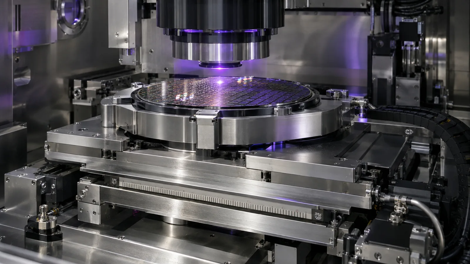
Alignment in a direct-write tool happens in stages, and each stage contributes its own error. The substrate is first loaded and pre-aligned, usually from its edge, notch or fiducial geometry, which establishes a coarse coordinate frame with a residual rotation and translation. The tool then captures alignment marks at known design locations, fits a transformation between the design coordinate system and the stage coordinate system, and applies it to the exposure job. Depending on the system, that transformation may be a simple offset and rotation, or a higher-order fit that also absorbs scale and small distortions of the substrate.
Field-level alignment is the second mechanism. A substrate larger than a single write field is patterned field by field, and each field can be aligned to its own local marks or positioned purely from the stage coordinate system. Local alignment corrects position errors that accumulate across the substrate, including substrate distortion and stage error, at the cost of additional mark captures and therefore additional time. Pure stage positioning is faster and is sufficient when the stage error over the relevant distance is small compared with the overlay allocation; it fails when the accumulated error is not. Most practical jobs use a hybrid: global marks to define the frame, local marks where the pattern's tolerance demands it.
The third mechanism is focus control, which is often treated as a separate subject but belongs in the overlay discussion. If the surface height varies across the substrate or between layers, the captured mark position can shift and the imaged feature can shift with it. Systems with active autofocus reduce this sensitivity substantially, but the autofocus has its own latency and its own error, and on sloped or reflective substrates those become part of the placement result rather than a separate concern.
An overlay budget is an allocation, and it is useful only if every term is written down with a number and a source. Start with the specification the device actually needs: the worst allowable placement error between two layers at the tightest feature, stated separately in X and Y. Then subtract the terms you cannot control and allocate the remainder. If the allocation is smaller than the known capability of a term, the design or the process must change, and discovering that on paper is far cheaper than discovering it on a patterned wafer.
Two terms deserve particular attention because they are frequently underestimated. The first is thermal drift. A long direct-write exposure can run for hours, and a substrate or stage that warms by even a fraction of a degree expands enough to matter at micrometre tolerances; the resulting error is usually systematic and radial rather than random, which is why it is easy to mistake for a design or scaling problem. The second is process-induced distortion, which appears after develop, etch, bake or bonding and therefore cannot be corrected by the exposure tool at all. It must be characterised separately and either compensated in the design or accepted in the budget.
The measurement itself also belongs in the budget. An overlay result reported without an instrument, magnification, calibration state and repeatability figure is not comparable with any other result. A disciplined team measures a reference target repeatedly, establishes the instrument's own repeatability, and reports overlay with that uncertainty stated. This is what prevents an apparent process regression from turning out to be a microscope that lost calibration.
Write the budget as a table before the first multilayer run:
The stage is the instrument that carries the pattern into position, and the encoder is how the control system knows where the stage is. Three encoder properties map directly into overlay. The first is accuracy: a scale error means the commanded field position is not the reached field position, and because the error is a function of position rather than of time, it produces the same offset on every substrate at the same location, which is a signature worth recognising. The second is repeatability, including servo settling: if the stage arrives at a field boundary with a residual that varies, the stitch varies. The third is resolution and noise: fine position noise is usually averaged out over an exposure, but it inflates the spread of the measured overlay rather than its mean.
A fourth contribution is geometric rather than electronic. Any Abbe offset between the encoder's measuring axis and the point being patterned converts angular error of the stage or structure into linear placement error at the substrate. On a stage with a large working distance or a tall sample stack, this term can exceed the encoder's own error, which is why mechanical design and metrology loop placement belong in an overlay review alongside the encoder specification. Straightness and flatness of the guide behave the same way: they are mechanical errors that the encoder faithfully reports while being unable to correct.
This is also where feedback architecture matters for long jobs. Encoder feedback with verified thermal behaviour and stable interpolation keeps the coordinate frame consistent across the hours a large exposure can take, and diagnostics from the feedback path make it possible to distinguish a stage event from a process event when an outlier appears. SENFU's lithography stages are built around the same optical encoder families used in its metrology products, and application engineering can state the stage positioning terms of the overlay budget for a specific configuration rather than leaving them implicit.
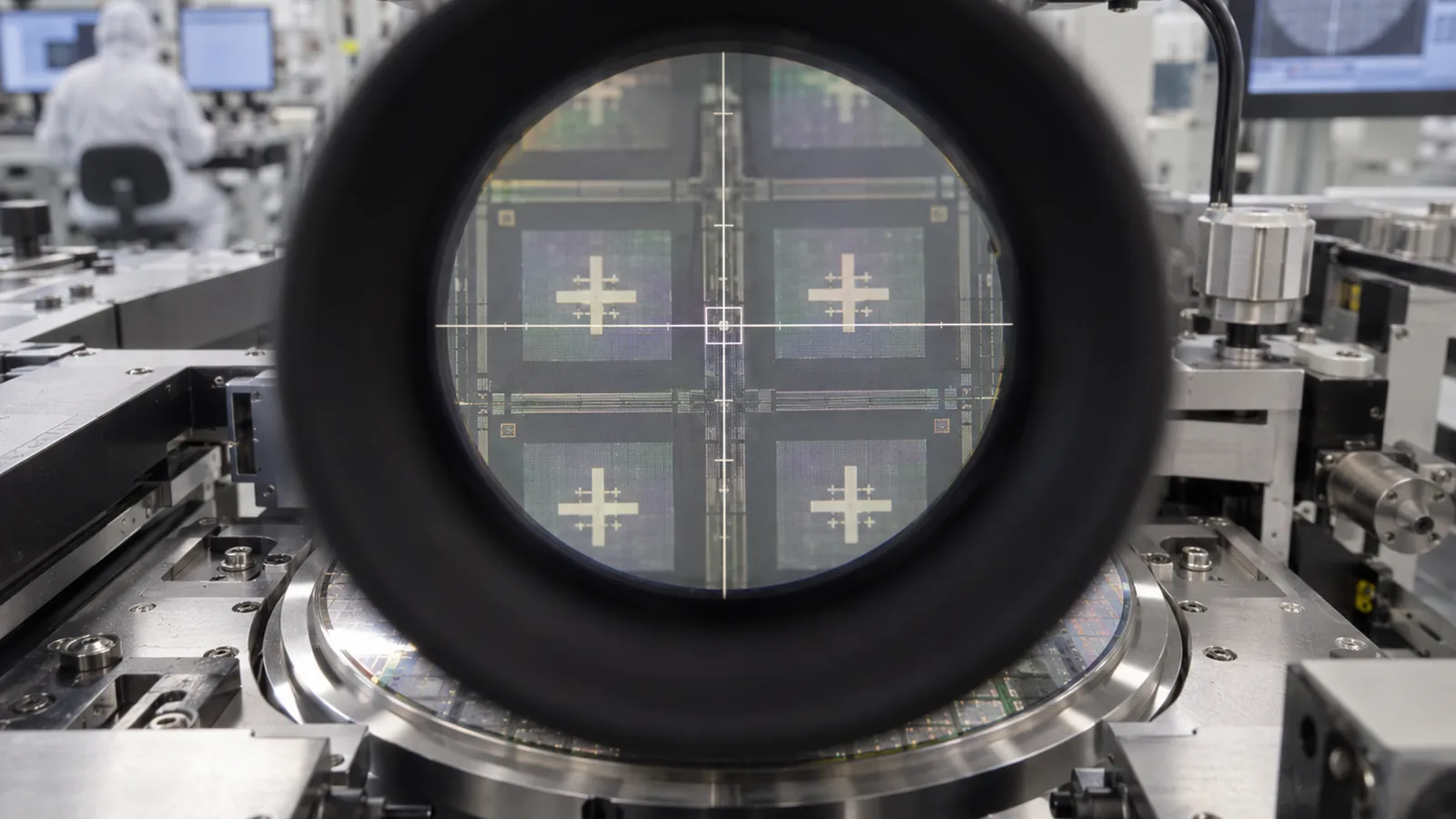
An acceptance test should be defined before the tool is used for production layers, and it should be repeatable by someone who did not design it. Use a designed overlay target placed across the substrate and across field boundaries: box-in-box or frame-in-frame structures at multiple positions, at least one inside each field and one straddling each boundary you care about. Expose the first layer, process it, expose the second layer with the production alignment strategy, then measure the residuals in X and Y at every target. Report mean and three sigma separately in each axis, and report the field-boundary targets separately from the interior targets, because they diagnose different terms.
Sampling should be honest about what it can detect. A handful of targets at the centre of the substrate will confirm that the tool works and will miss a systematic radial term entirely. A practical plan covers the centre, the mid-radius and the edge, includes at least one target in every field for small substrates, and includes enough repeat measurements at one location to establish the measurement repeatability. Where the process allows, run the acceptance twice with a thermal soak in between, because the difference between the two runs is often the clearest available estimate of the drift term.
Set the limits before the run, and write down what happens if a limit is exceeded. A useful acceptance record states the target design, the exposure settings, the alignment strategy and mark count, the measurement instrument and magnification, the calibration date, the sampling plan, the statistic, the measured values, and the disposition rule for each term. With that record in place, an overlay excursion six months later is a comparison against a baseline rather than an investigation from first principles. SENFU application engineering supports this by reviewing the target design and sampling plan with the customer and by stating the stage-side terms of the budget for the proposed configuration, so the acceptance test measures the complete system rather than only the exposure head.
CONCLUSION
Alignment in maskless lithography is a sequence of pre-alignment, mark capture, coordinate transformation, field-by-field positioning and focus control, and each step contributes its own error. The overlay result is the sum of those contributions plus substrate distortion, thermal drift, process effects and measurement uncertainty. Treating it as a single vendor number hides exactly the information needed when a multilayer device misses its target.
For a SENFU overlay review, send the layer stack, substrate and thickness, alignment-mark design, overlay requirement in X and Y, and the intended measurement method. SENFU application engineering can allocate the budget term by term, state the stage and encoder positioning terms for the proposed configuration, and help define an acceptance test with sampling, statistics and disposition rules that stays comparable for the life of the process.
SOLUTION ROUTES
EVIDENCE CHECKLIST
FAQ
Alignment accuracy describes how well the tool locates and fits to the alignment marks; overlay is the resulting placement error between two patterned layers. Overlay includes alignment, but also stage positioning, stitching, thermal drift, substrate distortion, process effects and measurement uncertainty, so a good alignment result does not guarantee good overlay.
Enough to define the coordinate frame and to absorb the distortion that matters: typically global marks spread across the substrate, plus local marks where the tolerance demands correction. More marks improves correction and costs exposure time, so the count should follow the overlay allocation and the observed substrate distortion rather than a default.
Field boundaries accumulate stage positioning error, settling residuals and any thermal state change during the seam, and they are where stitching error appears. Measuring targets that straddle boundaries separately from interior targets is the fastest way to separate a stitching problem from a global alignment problem.
The encoder defines the coordinate frame the stage moves in. Scale and accuracy errors produce position-dependent offsets that repeat on every substrate, settling and repeatability errors vary the stitch, and position noise inflates the measured spread. Mechanical Abbe offset between the measuring axis and the substrate converts angular error into placement error, often larger than the encoder error itself.
Report mean and three sigma separately in X and Y, over a defined sampling plan, with the measurement repeatability stated. A single scalar hides systematic terms: a small spread with a large mean indicates a correctable offset, while a large spread with a small mean indicates a stability or metrology problem.
Not in the exposed layer. It can be reduced by thermal soak and environment control before the exposure, absorbed by local alignment during the exposure, and compensated in subsequent layers or in the design once measured. The practical step is to measure drift over the longest expected job and allocate it explicitly in the budget.
AUTHORITATIVE SOURCES
TECHNICAL REVIEW
Send the application, critical parameters and any drawing or process information available.
Discuss your application ↗