
Dose-plane irradiance
Require irradiance at the resist plane for the stated optics and wavelength, not source flux, and confirm it supports the target dose within an acceptable exposure time.
TECHNOLOGY / LITHOGRAPHY LIGHT SOURCES
The exposure source sets dose control, throughput, linewidth stability and resist compatibility in a maskless lithography system. This guide compares 405 nm LEDs and UV diode lasers on power, lifetime, intensity stability and resist matching, and lists the evidence to request before specifying either.
Published
DIRECT ANSWER
In a maskless lithography system the light source converts electrical power into a dose delivered on photoresist, so the selection question is not which device is brighter but which one holds its irradiance, wavelength and beam behaviour inside the process window over years of duty. A 405 nm LED gives a compact, incoherent, low-speckle source with modest irradiance and slow, monitorable lumen decay. A UV diode laser gives far higher irradiance and coupling efficiency into the imaging optics, at the price of coherence effects, faster drive electronics and stricter thermal and current stability.
Specify the source against four measurable requirements: sufficient irradiance at the resist plane for the target dose and exposure time, an intensity stability figure over minutes and over months, a lifetime statement with test conditions, and a wavelength and bandwidth that the chosen resist actually absorbs. Then require the monitoring method that will detect drift before it moves linewidths, and the replacement route when the source reaches end of life.
ENGINEERING CONTEXT
Light source datasheets invite a comparison that the process cannot support. A radiant flux figure says nothing about what reaches the resist plane through the illumination optics; a lifetime hour rating says nothing about intensity stability during the exposure that sets a linewidth; a wavelength label hides a bandwidth that may or may not overlap the resist absorption. Because maskless systems write pattern after pattern without the averaging of a flood exposure, a slow drift in source output moves dose, and dose moves linewidth, sidewall and sensitivity, until development results change for reasons no operator can see. The confusion is compounded when LED and laser options are quoted in different units, at different points in the optical path, and with different stability assumptions. The buyer who asks only for power and price discovers the real trade-offs in process qualification, when exposure times stretch or critical dimensions drift. The fix is to translate every source claim into dose-plane terms and to make stability, lifetime conditions and monitoring part of the purchase specification.
Discuss your requirement ↗CRITICAL REQUIREMENTS
Require irradiance at the resist plane for the stated optics and wavelength, not source flux, and confirm it supports the target dose within an acceptable exposure time.
Ask for short-term intensity stability over a single exposure and long-term drift over months of duty, with the measurement method and bandwidth stated.
Obtain L70 or equivalent luminous or radiant maintenance data for the exact source at the drive current, duty cycle and temperature of the installed module.
Confirm source centre wavelength and bandwidth against the absorption spectrum of the intended resists, including sensitivity, contrast and expected dose.
BUYER MATRIX
Give every shortlisted supplier the same process definition and request configuration-specific proof.
| Selection factor | 405 nm LED | UV diode laser |
|---|---|---|
| Irradiance at resist plane | Moderate; exposure time set by dose and optics transmission | High; supports short exposures and higher dose budgets |
| Coherence and speckle | Incoherent, low speckle, forgiving of imaging defects | Coherent; speckle and interference must be managed by design |
| Wavelength and bandwidth | Centre near 405 nm with a bandwidth of tens of nanometres | Narrow linewidth near the stated wavelength; mode stability matters |
| Intensity stability | Slow lumen decay, monitorable; thermal drift with duty cycle | Fast noise and drift controlled by current and temperature regulation |
| Lifetime behaviour | Gradual decay described by L70 with stated conditions | Gradual decay plus sudden failure modes; spare policy advisable |
| Drive and thermal design | Simple constant-current drive, manageable heat load | Precision current and temperature controllers, stricter supply quality |
| Typical fit | General R&D direct write, broad resist compatibility, long duty cycles | High-dose or high-throughput writing, fine dose control, fast patterning |
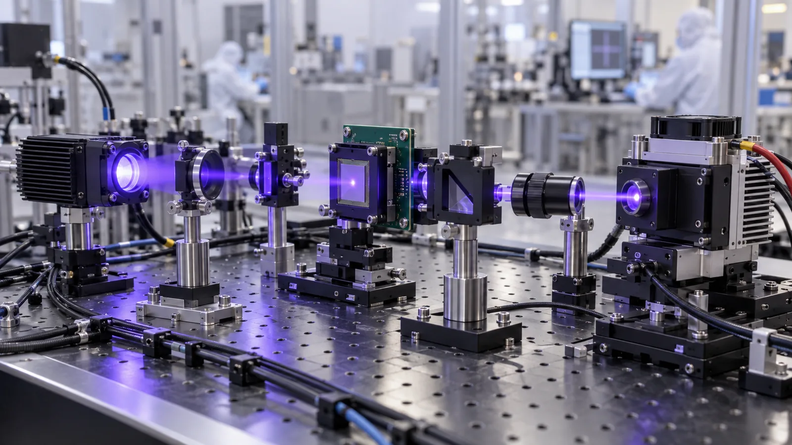
A maskless lithography system shapes light from the source into the pattern through a digital micromirror device or scanning optics, then images it onto the resist. Everything the process cares about is delivered at the resist plane: irradiance, uniformity, wavelength and stability. The source therefore does not act alone. Optics transmission, filter selection, source étendue and the modulation scheme all sit between the datasheet and the dose, which is why a brighter device does not automatically mean a faster or more stable tool, and why comparisons quoted at the source aperture mislead.
This placement also means source behaviour enters the process twice. Instantly, as intensity noise and thermal drift within a single exposure, moving dose between the first and last field of a wafer. And slowly, as the source ages, so a process qualified in the first quarter quietly degrades by the fourth. A selection that ignores either window pushes the problem into development results, where linewidth changes are expensive to trace back to the light.
Near-UV LEDs around 405 nm are the workhorse source for direct-write systems aimed at standard positive resists and SU-8-style chemistries. Their strengths are structural: the emission is incoherent, so speckle and interference fringes do not disturb the aerial image; the device is compact and runs from a simple constant-current driver; and the heat load can be managed with conduction rather than elaborate cooling. The bandwidth of tens of nanometres overlaps the absorption of common g-line and h-line-adjacent resists well enough for reproducible exposure.
The weaknesses are irradiance and decay. Radiant output per device is modest, so exposure time scales with dose requirement and optical transmission, and throughput falls on thick or low-sensitivity resists. Output decays gradually with lumen maintenance behaviour described by L70 figures, and shifts with junction temperature, so duty cycle and cooling design belong in the stability conversation. Both effects are slow and monitorable, which makes the LED forgiving in systems with dose feedback.
Diode lasers in the violet and near-UV deliver orders of magnitude higher irradiance than LEDs and couple efficiently into the illumination optics, which is why they appear in high-throughput and high-dose writers. The narrow linewidth gives precise wavelength control for resists selected around it, and the small source étendue supports efficient beam shaping and scanning architectures. Exposure times that an LED system spends waiting can be spent writing.
The costs are coherence and sensitivity. Speckle and interference must be suppressed by optical design, despeckling or averaging, or they appear as linewidth roughness that no dose calibration removes. Output depends steeply on drive current and junction temperature, so stability is bought with precision current sources, thermoelectric control and feedback monitoring rather than with component selection alone. Diodes also combine gradual decay with sudden failure modes from facet damage and drive faults, which makes a spare-and-replacement policy part of the architecture rather than an afterthought to be arranged when the first failure occurs.
Dose is irradiance multiplied by time, so the useful comparison between sources is irradiance at the resist plane for the same optics, field and wavelength, not radiant flux at the source aperture. A resist needing thirty millijoules per square centimetre under a source of one milliwatt per square centimetre waits thirty seconds; under ten it waits three. Throughput follows directly, and so does the practicality of thick resists, multi-pass strategies and grayscale exposures that spend dose on profile control.
The honest check is a dose budget for the intended process: resist sensitivity at the actual wavelength, optics transmission, fill factor of the modulation scheme and the acceptable exposure time per field. Ask suppliers to state irradiance at the plane and the measurement method behind it. A figure quoted at the source, or at a different wavelength than the resist sees, will move the throughput estimate by factors, not percentages.

Linewidth is a function of dose, and dose is a function of source output, so stability belongs in the specification with two separate windows. Short-term stability, over the duration of a single exposure, sets field-to-field consistency; slow drift, over weeks of duty, moves the process until a recalibration or feedback loop corrects it. LEDs drift mainly with junction temperature and ageing, in trends that integrate nicely with a monitored dose calibration; lasers add fast noise and mode behaviour that demand regulation bandwidth from the drive electronics. Both windows should be stated with numbers and a measurement method, because adjectives such as stable cannot be qualified against.
What makes stability a purchase issue is detectability. Require the tool to monitor delivered intensity or energy per exposure in a documented format, to log it, and to alarm on deviation from the qualified window. With that record, drift becomes a scheduled recalibration instead of a yield investigation. Without it, the first symptom is a linewidth that no longer matches the process of record, and the root cause sits in a component nobody measured.
Resist matching is the final filter on the decision. The source centre wavelength and bandwidth must overlap the resist absorption spectrum with enough margin for the exposure dose to land where the chemistry expects it; sensitivity, contrast and contrast curve data should be quoted for the actual source spectrum, not for a nominal wavelength. Standard positive resists, image-reversal chemistries and thick epoxy-based resists each behave differently across the near-UV, and a source that works for one class may be marginal for another.
Then match the source to the workflow. For R&D platforms with frequent resist changes, varied substrates and dose-feedback calibration, the LED route offers stability and simplicity; for production-oriented writing where exposure time dominates cost, the diode laser pays for its control electronics in throughput. Request the stability, maintenance and replacement evidence for both options on the same terms, and the decision usually becomes an obvious fit rather than a close call.
CONCLUSION
Choose the exposure source by what it delivers at the resist plane, not by the number on the device datasheet. Define the dose budget, the two stability windows and the resist spectrum first, then require irradiance, stability and lifetime evidence on those same terms, with a monitoring method and a replacement route in writing. A source selected this way supports the process for years instead of defining its first drift investigation.
EVIDENCE CHECKLIST
FAQ
For most R&D direct-write processes with standard resists, yes, provided the dose budget and acceptable exposure time are checked against irradiance at the resist plane rather than against source flux. Throughput-heavy production writing and thick, low-sensitivity resists are where the LED's limited irradiance first becomes a real constraint.
An LED emits incoherently, so no stable interference pattern forms in the aerial image. A diode laser is coherent, and interference between scattered paths produces speckle that must be suppressed by optical design or averaging, or it appears as linewidth roughness.
Two separate figures with stated conditions: short-term intensity stability over a single exposure, which sets field-to-field consistency, and long-term drift over months of representative duty, which the dose feedback must correct. Ask for the measurement method, sampling bandwidth and the qualification window behind both numbers.
LEDs decay gradually and are well described by lumen maintenance figures such as L70 at stated current and temperature. Diode lasers also decay but add sudden failure modes from facet and drive faults, so both a stability specification and a spare policy are appropriate.
Some architectures combine sources for different writing modes, but each source then needs its own calibration, monitoring and qualification within the process. The additional complexity is justified only when the workflows genuinely need both irradiance and the LED's stability profile.
AUTHORITATIVE SOURCES
TECHNICAL REVIEW
Send the application, critical parameters and any drawing or process information available.
Discuss your application ↗