
Cold-state optical alignment
Gap, tilt and yaw defined at the operating temperature, with the differential contraction between scale, carriage and readhead bracket calculated rather than assumed.
TECHNOLOGY / CRYOGENIC FEEDBACK
Position feedback that worked at room temperature can fail inside a cryostat. This guide explains how differential thermal contraction, adhesive behavior, the optical power budget and cold cabling affect an optical encoder, and how to specify, install and verify one for low-temperature operation.
Published
DIRECT ANSWER
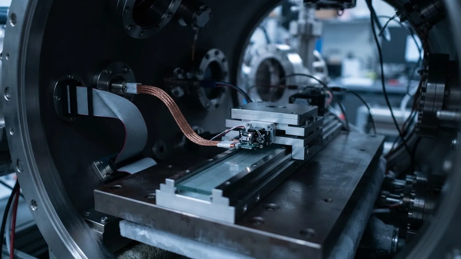
A cryogenic optical encoder is not a standard encoder that simply happens to be cold. Below roughly 100 K, materials stiffen, adhesives change modulus, differential thermal contraction between scale, carriage and readhead housing reaches hundreds of micrometres per metre, and the light source must still deliver enough optical power at a wavelength the detector can use. The encoder can work very well in cryogenic vacuum, but only when scale substrate, adhesive or clamp, optical gap, cabling and thermal path are all designed for the cold state rather than the warm assembly state.
The practical rule is to verify feedback at operating temperature, not at 293 K. A diffraction-grating scale bonded to a differentially contracting base shifts its pitch; a readhead whose bracket contracts differently from the scale changes its gap; and a compliant adhesive that cured correctly warm can crack or creep when cooled. Specify the cold-state gap and alignment, qualify the assembly with a full temperature cycle, and treat the room-temperature datasheet as a starting point rather than the proof of performance.
ENGINEERING CONTEXT
A nanopositioning stage inside a cryostat is aligned and validated warm, then cools down and the encoder loses signal, trips an amplitude alarm, or reports a scale factor that no longer matches the interferometer by a large margin. Nothing was obviously wrong with the design at room temperature: the readhead gap was nominal, the scale was flat, and the adhesive was the same one used on every other axis. The failure is thermal rather than electrical. Every dimension in the optical path changes by a different amount because every material has a different coefficient of thermal expansion, and the encoder has no way to compensate for a gap or a pitch that moved after the last calibration. Predicting and controlling those changes is a design task that must be closed before assembly, because rework inside a cryostat is slow, risky and expensive.
Discuss your requirement ↗CRITICAL REQUIREMENTS
Gap, tilt and yaw defined at the operating temperature, with the differential contraction between scale, carriage and readhead bracket calculated rather than assumed.
Scale substrate, adhesive or clamp and every bonded joint selected for the cold cycle, with modulus, glass-transition behavior and cracking risk reviewed for the actual temperature range.
Light source output, detector response, interpolation quality and automatic gain behavior confirmed at the cold setpoint instead of extrapolated from a warm laboratory measurement.
Low-outgassing, thermally anchored cabling and a defined conduction path so that the readhead and any nearby electronics stay inside their operating range.
BUYER MATRIX
Give every shortlisted supplier the same process definition and request configuration-specific proof.
| Element | Effect of cooling | Design response | Evidence to request |
|---|---|---|---|
| Scale substrate | Grating pitch and scale length change with contraction; bonded scale follows the base | Match scale substrate to the base or model and accept the residual expansion | Expansion data over the operating range |
| Adhesive or clamp | Modulus rises, some adhesives crack or creep, clamp preload changes | Use a cold-qualified adhesive or a compliant clamp with defined preload | Cure schedule and cold-cycle test result |
| Readhead gap | Bracket and scale contract differently, so the optical gap moves | Set the warm assembly target from the calculated cold gap | Cold-gap calculation and gap measured after cooldown |
| Light source and detector | Emission and responsivity shift, optical margin may fall | Confirm the optical budget at the cold setpoint and set realistic alarms | Signal amplitude and gain behavior at temperature |
| Cable and connector | Jackets stiffen, micro-cracks form, flexibility is lost | Anchor cables thermally and use qualified low-temperature materials | Material declaration and flex test at temperature |
Encoder specifications are measured on a stable fixture at room temperature. That fixture fixes the readhead gap, the scale pitch and the alignment so the optical and interpolation performance can be characterised. A cryogenic axis breaks all three assumptions at once: the gap changes, the pitch changes and the alignment changes, each by a different amount, and the changes have already happened by the time the stage reaches its working temperature.
The single most important number in a cryogenic encoder axis is the difference in contraction between the scale and the surface it is fixed to. A glass or glass-ceramic scale and an aluminium base shrink by very different amounts between room temperature and 4 K, and if the scale is bonded rigidly along its length, that difference is stored as stress in the scale and the bond line. The scale may bow, the bond may creep or crack, and the effective grating pitch changes in a way the encoder cannot detect. The design answer is either to match the substrate and the base so the differential is small, or to fix the scale at a single point and let it expand and contract freely in the long direction.
Adhesives deserve the same scrutiny as the scale. An adhesive that is compliant and reliable at room temperature can pass through its glass transition on the way down, becoming brittle, or it can contract faster than the materials it joins and open a void at the edge of the bond. Where the assembly must survive many thermal cycles, a mechanical clamp with a controlled, temperature-stable preload is often more predictable than glue, provided the clamp itself does not impose point loads that distort the grating locally.
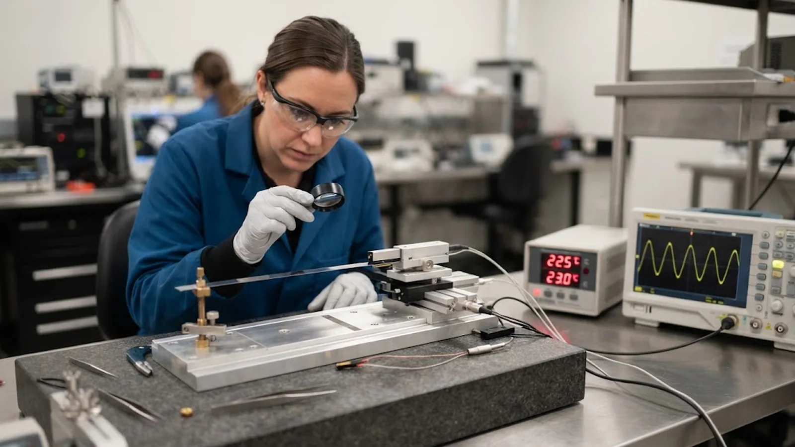
An optical readhead works because a light source illuminates the grating and a detector converts the resulting intensity pattern into electrical signals. Cooling affects both ends of that chain. Light source output changes with temperature, detector responsivity shifts, and the analogue signal amplitude available for interpolation can fall or rise depending on the specific devices. If the amplitude drops below the level the interpolator needs, resolution degrades and the position output becomes noisy long before a hard alarm appears.
Everything installed in a cryostat is a thermal path as well as a mechanical part. Cables feeding the readhead conduct heat unless they are anchored, and standard jacketed cables become stiff and fragile when cold. A cable that flexes happily on a bench can crack its insulation after a few cooldowns, and a cable that is not strain-relieved can pull the readhead out of alignment as it contracts. Route the cable with slack that accommodates contraction, anchor it to an intermediate temperature stage, and confirm that the jacket and connector materials are qualified for the environment.
Contamination control runs alongside the thermal work. Any adhesive, lubricant or polymer component that releases volatiles can condense on cold optics and on the grating itself, reducing signal or creating a slow drift over time. Materials intended for vacuum service should be selected on that basis, and the assembly should be cleaned and, where the process allows, given a low-temperature bake before final closure.
A cryogenic axis should be qualified with a defined cycle: assemble warm, record the baseline alignment and signal, cool to the working temperature, hold long enough for the assembly to stabilise, and then measure alignment, gap, signal and position error again. This single cooldown, repeated over a few cycles if the assembly must survive many, separates reversible thermal effects from permanent changes such as adhesive creep or a loosened clamp. The cold measurement is the one that matters for the process; the warm measurement is only a convenient reference point.
Verification at temperature needs a reference that is trustworthy when cold. A laser interferometer whose own optics and laser head are outside the cold zone, or an on-axis reference structure, avoids the trap of calibrating the cold encoder against an instrument that is itself changing. Record the position error, the gap and the signal together, because the three explain each other: a gap change shifts the scale factor, an amplitude change limits resolution, and an alignment change introduces a direction-dependent offset. Sensible documentation of that trio turns cryogenic feedback from a recurring mystery into a bounded engineering property.
CONCLUSION
An optical encoder can deliver reliable position feedback at cryogenic temperatures, but only when the axis is designed around the cold state instead of the assembly state. Differential contraction sets the scale pitch and gap, adhesive behavior sets the stability of the bond, and the light source and detector set the optical margin that the interpolation depends on.
Design the cold gap and alignment on paper, choose scale substrate, adhesive or clamp and cabling for the working temperature, verify signal and position error during a controlled cooldown, and set alarms against the cold baseline. An axis managed this way keeps its resolution, its accuracy and its repeatability all the way down, instead of working only until the first cooldown.
EVIDENCE CHECKLIST
FAQ
Not without review. The readhead electronics, the scale substrate, the adhesive or clamp and the cabling all have temperature limits and behaviors that differ from room temperature. A configuration can usually be adapted, but the working temperature, cycle count and vacuum environment must be stated so the materials and optical gap can be selected for that condition.
Resolution itself is a property of the interpolation electronics and the scale pitch, but the achievable signal quality depends on optical amplitude, which changes with temperature. If the amplitude falls at the cold setpoint, noise rises and the effective resolution degrades. Confirming the signal budget at temperature is what tells you whether the specified resolution is realistic.
Both can work. Bonding gives an even, low-profile fixing when the differential contraction between scale and base is small and the adhesive is qualified for the cold cycle. Clamping with a controlled preload is often more predictable when materials differ strongly or when the assembly must survive many cycles.
Provide the operating temperature and cycle count, the vacuum level, the scale length and travel, the base material, the mounting space, the required resolution and accuracy, and any warm or cold test data. SENFU can recommend scale substrate, fixing method and cable construction, and propose a temperature verification plan for the assembled axis.
AUTHORITATIVE SOURCES
TECHNICAL REVIEW
Send the application, critical parameters and any drawing or process information available.
Discuss your application ↗