
Pressure envelope
State base pressure, process pressure, gases, dwell time and any exposure to plasma or radiation.
APPLICATION / VACUUM MOTION
Build a defensible vacuum encoder specification around pressure, materials, cable, bakeout, thermal paths and measured contamination evidence.
Published
DIRECT ANSWER
Qualify a vacuum encoder by defining the actual pressure range, process gases, temperature and bakeout—not by accepting a generic ‘vacuum compatible’ label. Request the material and cable declaration, adhesive and lubricant controls, connector construction, outgassing or RGA evidence, thermal limits and the exact configuration covered by each result.
The acceptance test should run the encoder and motion axis in a representative chamber or a documented surrogate. Measure base pressure recovery, RGA species, signal integrity, thermal drift and repeatability before and after bakeout. Separate data supplied by the encoder manufacturer from data generated on the assembled stage; chamber volume, pumping speed and nearby materials can dominate the result.
ENGINEERING CONTEXT
Vacuum motion turns an optical encoder into part of the contamination budget and the heat path. A mechanically small device can still introduce cable, adhesive, lubricant or connector materials that outgas, and the lack of convection changes how the readhead and scale reach temperature.
Discuss your requirement ↗CRITICAL REQUIREMENTS
State base pressure, process pressure, gases, dwell time and any exposure to plasma or radiation.
Control metals, polymers, adhesives, lubricants, cable jackets, connectors and fasteners.
Define temperature, ramp, duration, heat path and the position signal during conditioning.
Request RGA or outgassing data and repeat the qualification on the integrated stage.
BUYER MATRIX
Give every shortlisted supplier the same process definition and request configuration-specific proof.
| Item | Buyer evidence | Failure mode |
|---|---|---|
| Pressure | Exact pressure range and configuration | A rating is applied outside its tested range |
| Materials | Full material, adhesive, cable and lubricant list | Unknown species contaminate the chamber |
| Bakeout | Temperature, time, ramp and recovery data | Seal or cable damage changes the signal |
| RGA | Baseline and post-bake spectra with chamber conditions | Device data is confused with chamber background |
| Thermal | Scale/readhead temperature and drift method | Position shifts without air cooling |
| Service | Replacement and clean handling procedure | Maintenance invalidates qualification |
Identify whether the encoder sits inside the chamber, in a load lock, behind a feedthrough or outside the vacuum boundary. The boundary determines which materials, connectors and cable sections need outgassing evidence. Record base pressure, process pressure, gas chemistry, pump-down time, dwell time, bakeout and any exposure to plasma, ultraviolet light or radiation. A supplier cannot qualify a configuration from the word ‘vacuum’ alone.
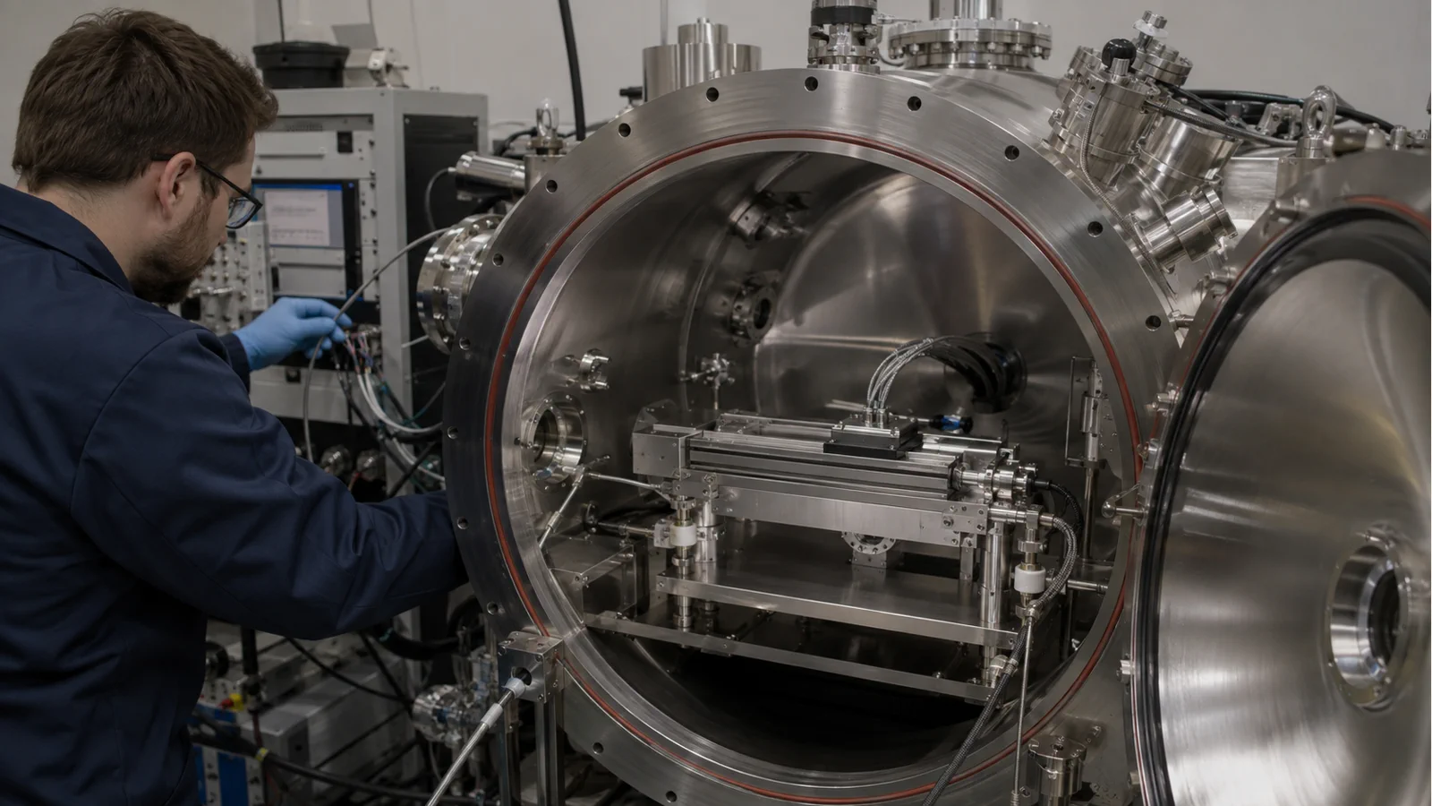
Draw the chamber cross-section and mark the encoder, scale, cable, connector, adhesive, feedthrough, grease and nearby stage materials. Include surfaces that face the wafer or beam path. This identifies hidden contributors such as a cable loop under a cover or an adhesive pad used during assembly. It also makes it possible to separate encoder evidence from the rest of the chamber during the test.
Request the material family for scale, readhead housing, optics, cable jacket, connector, adhesive, lubricant and fasteners. ‘Metal body’ is not enough if a polymer insert or potting compound is inside. Ask which items are user-supplied and which are included in the quoted configuration. If a material is proprietary, request an outgassing declaration or a test report instead of an unsupported assumption.
Keep cleanliness and handling in the same document. Specify cleaning solvent, bakeout preparation, gloves, packaging and the time between cleaning and pump-down. The qualification is only useful if production can repeat the preparation. A clean test sample with a different cable or adhesive does not qualify the delivered assembly.
Residual gas analysis is useful only when the chamber state and test sequence are recorded. Establish a clean-chamber baseline, install the encoder configuration, pump down, run the agreed temperature cycle and compare the spectra. Note chamber volume, pumping speed, sensor location, blank time and any nearby process material. The same device can appear different in a small test vessel and a production chamber.
Ask the supplier which species and reporting convention are used and whether the result is a coupon, a complete readhead, a cable assembly or an integrated stage. Keep raw traces and the configuration revision. If the report is old or covers a different adhesive or connector, treat it as background evidence and plan a system-level test.
Bakeout removes volatile species but can also change adhesives, cable jackets, seals and alignment. Define the maximum temperature, ramp, duration and allowed gradients for the encoder configuration. Measure signal quality and position before, during and after the cycle if the device is powered, or define a post-bake alignment check if it is not. A vacuum-ready assembly needs a thermal plan as well as a materials list.
The scale and stage can also change length with temperature. In a convection-free chamber, heat travels through mounts, cables and the stage structure. Place sensors where the process datum and the scale actually are, and record warm-up time. If compensation is used, document the reference temperature and the conditions under which it was derived.
Vacuum changes thermal behavior but does not remove EMC risk. Route the encoder cable away from motor phases, heaters and switching supplies, define shield termination and verify the controller input at the installed cable length. Monitor diagnostics, dropouts, noise and reference marks during pump-down, motion, valve operation and bakeout. Record whether the encoder is incremental or absolute and how errors are latched and cleared.
For an absolute BiSS-C configuration, include clock quality, frame error, latency and startup validity. For incremental feedback, include differential amplitude, index repeatability and count loss during direction changes. The test should use the real controller and firmware revision so that electrical and software behavior are not left to a later commissioning stage.
After the chamber reaches the operating state, compare encoder position with an independent reference over the motion range. Test the readhead at both ends, repeat target points in both directions, and include the warm-up and pressure transitions used in the recipe. Use the same approach, settling and metrology rule in every run. A static count check cannot expose scale drift or mounting movement.
Keep pressure, temperature, RGA, reference readings, encoder diagnostics and motion commands in one record. If a failure appears, the team can tell whether it follows a gas event, a thermal step, a cable movement or a mechanical shift. This evidence is more valuable to procurement than a generic vacuum badge because it describes the delivered system.
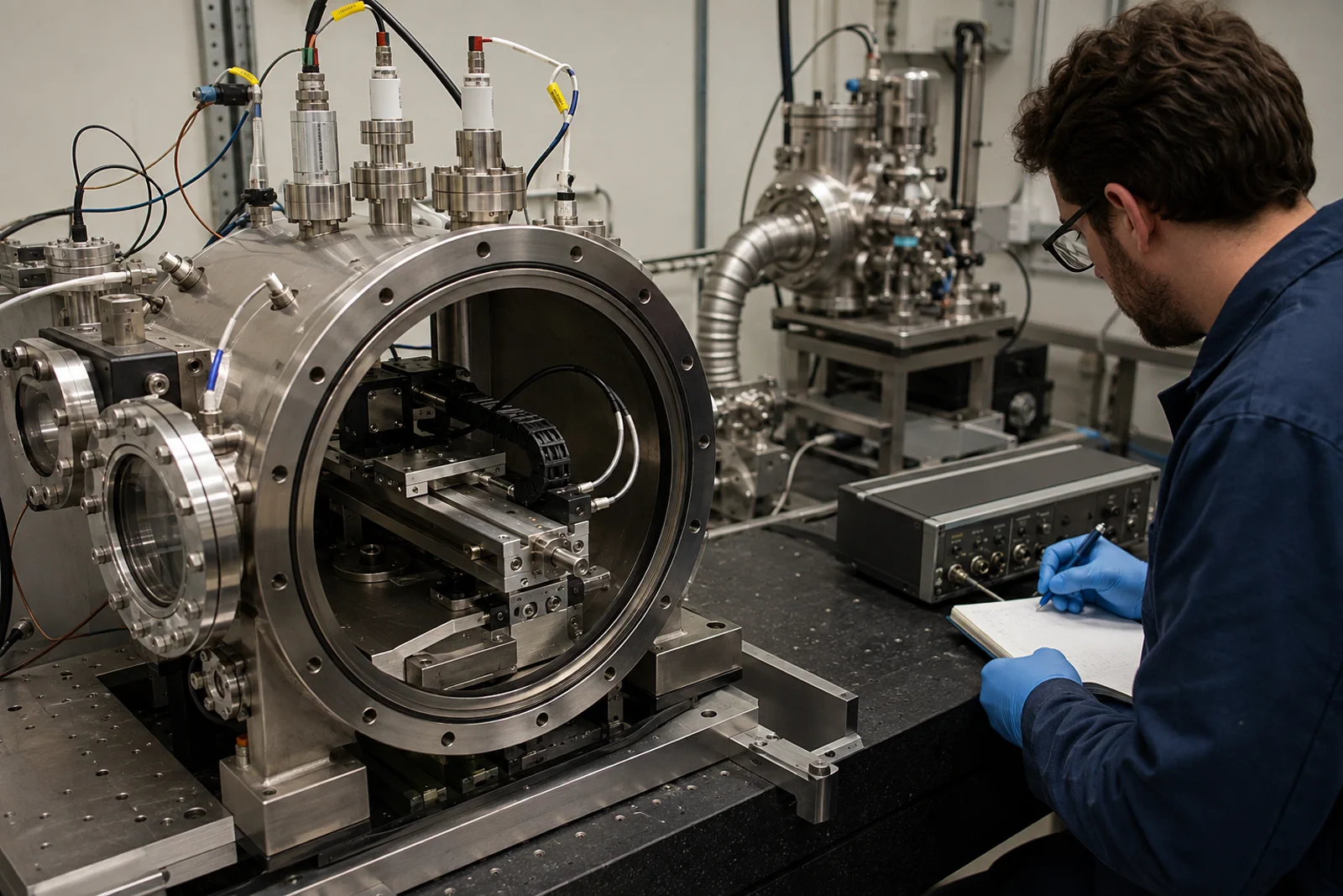
Vacuum qualification ends only when the service process is defined. Specify how the encoder is removed, cleaned, packaged, reinstalled and realigned, and which seals, cables or adhesives are replaced. Mark items that invalidate the original RGA or bakeout evidence. Keep revision-controlled drawings and a serial-number record for traceability.
If the stage changes, repeat the relevant part of the qualification. A new cable length, connector, lubricant or cover can change both outgassing and signal behavior. Procurement should budget the re-test rather than assuming that a previous chamber run covers every future configuration.
Give suppliers the pressure and process envelope, chamber drawing, temperature and bakeout schedule, cable route, controller, travel, speed, cleanliness and acceptance reference. Ask them to identify guaranteed, typical, calculated and process-dependent values. Require the exact model and configuration on every report and request the evidence pack before a purchase order is released.
SENFU supplies encoder configurations for precision motion and vacuum-oriented applications, but the final qualification must be tied to the delivered assembly. A clear brief prevents a generic ‘UHV capable’ phrase from being copied into a purchase specification without the materials, RGA and thermal evidence needed by the facility.
CONCLUSION
Vacuum encoder qualification is a materials, thermal, signal and contamination exercise. Define the boundary, request configuration-specific evidence, separate chamber background from device data and test the integrated stage after the real bakeout and motion sequence.
SENFU can help map the pressure and motion requirement to an encoder configuration and identify which material, RGA, thermal and repeatability records should accompany procurement.
SOLUTION ROUTES
EVIDENCE CHECKLIST
FAQ
No. Require the pressure range, materials, cable, connector, bakeout and test conditions for the exact configuration.
Not automatically. Chamber volume, nearby materials, pumping and installation affect the result. Use the report as component evidence and repeat a representative system test.
Heat changes scale and stage dimensions and can also alter adhesives, cables or alignment. Record temperature at the process datum and the scale and verify position after conditioning.
Monitor pressure, temperature, RGA, encoder diagnostics, signal quality, reference marks and independent position while the actual motors and valves operate.
Only if the service procedure and replaced parts are covered by the qualification. A new cable, adhesive, connector or mounting can require a partial or full re-test.
AUTHORITATIVE SOURCES
TECHNICAL REVIEW
Send the application, critical parameters and any drawing or process information available.
Discuss your application ↗