Optical Encoder Index Pulse: I0 Homing, Latching, and Zero-Referencing for Precision Stages
The index (I0/one-per-rev) pulse on an optical encoder provides a repeatable mechanical datum that incremental A/B channels alone cannot supply. This guide explains what the index pulse is, how width and validity window specifications constrain its use, how index-on-the-fly latching with the A/B channel state reconstructs a unique position, where error sources—index width tolerance, propagation delay, and trigger jitter—enter the homing repeatability budget, and a practical setup checklist for precision stages.
Published
DIRECT ANSWER
What should a buyer prioritize?
The index pulse (also called Z, I0, or one-per-rev) is a single, narrow output pulse that an optical encoder generates once per mechanical revolution on a rotary axis, or once per reference mark on a linear scale. Unlike the A and B quadrature channels, which count displacement but carry no absolute datum, the index is tied to a fixed mechanical location: it repeats at exactly the same position within every signal period, and its edge is specified by the manufacturer to occur at a defined state of the A/B channels. That relationship is what makes the index useful—it converts an otherwise position-blind counting system into one with a repeatable zero reference.
Used correctly, the index enables two things on precision stages: homing, where the axis searches for the index to establish a machine zero, and index-on-the-fly latching, where the controller captures the A/B channel state at the index edge to reconstruct a unique, fine-resolution position. Both depend on specifications that are easy to overlook—index pulse width and its tolerance, the validity window in which the A/B state is qualified, propagation delay asymmetry between channels, and trigger or sampling jitter. Each contributes to the homing repeatability budget, which for a well-executed switch-gated index homing sequence on a precision stage is typically a few counts of the finest interpolated resolution rather than the full signal period.
ENGINEERING CONTEXT
The decision starts with the real constraint.
An incremental encoder without its index used is a machine with no memory of where zero is. Power cycles, servo faults, and any loss of counts leave the controller holding a position value that is correct relative to nothing. Engineers who skip a rigorous index implementation discover the consequences as drift between power-ups, parts referenced inconsistently after each home, or overlay errors in lithography and metrology applications that appear randomly and cannot be traced to the mechanical system. The traps are subtle. The index pulse has a finite width with a manufacturing tolerance, so at high axis speed the pulse may be shorter than the controller's sampling interval and never be seen at all. The A/B state that qualifies the index is only valid inside a defined window; sample it outside that window and two passes home to positions one signal period apart. Index and A/B channels travel different physical paths with different propagation delays, so a simultaneous electrical event arrives at the latch as two slightly different times. Trigger jitter in the latching hardware adds noise that no amount of software filtering fully removes. Each of these terms is individually small, but an undocumented homing sequence that relies on all of them at once can easily produce repeatability an order of magnitude worse than the encoder's datasheet numbers, and the difference only appears after the machine is installed.
Pulse width in electrical degrees or linear units, its tolerance, the gating relationship to A/B (which state qualifies the index), and whether the index is gated or ungated must all be documented before the homing logic is written.
02
Latch hardware able to capture A/B and index simultaneously
Index-on-the-fly operation requires that the A/B state and the index edge are sampled by the same hardware event, with matched propagation paths and trigger jitter small against the intended repeatability budget.
03
Defined homing approach direction and velocity
The homing sequence must fix the direction of travel, the search velocity, and the deceleration behavior after the index is found, because approach velocity and motion settle-out dominate the repeatability of the final reference position.
04
Verification against a measured repeatability budget
The implemented homing sequence must be tested over repeated power-up and re-home cycles, with the scatter measured against a budget that names each contribution—index width tolerance, delay asymmetry, jitter, velocity, and mechanical settle.
BUYER MATRIX
Compare evidence, not feature labels.
Give every shortlisted supplier the same process definition and request configuration-specific proof.
Index-based homing strategies compared
Aspect
Index-only search
Limit-switch-gated index
Index-on-the-fly with A/B latch
Principle
Axis travels at low speed until the index edge triggers; zero is set from the raw index pulse
Axis moves toward a limit switch, reverses at low speed, and takes the next index pulse as the datum
Axis crosses the index at constant velocity while hardware latches the A/B channel state at the index edge, reconstructing a fine-resolution position
Repeatability drivers
Search velocity, index width in time, controller sampling
Switch mechanical repeatability plus index terms; the switch only gates, the index sets the datum
Latch jitter, propagation delay asymmetry, velocity stability across the index
Typical repeatability
Fraction of a signal period at sufficiently low speed
A few counts of the interpolated resolution when switch gating is consistent
Best of the three; limited by latch electronics rather than the index mark itself
Cycle time
Longest; slow search over the full travel segment
Medium; fast approach, then a short slow reverse segment
Short; a single constant-velocity pass is sufficient
Best use
Simple axes, low speeds, coarse zero requirements
Standard machine axes with defined home regions and moderate repeatability requirements
Precision stages, lithography and metrology machines, and any axis whose zero must reconstruct to the finest resolution
What the index pulse actually is
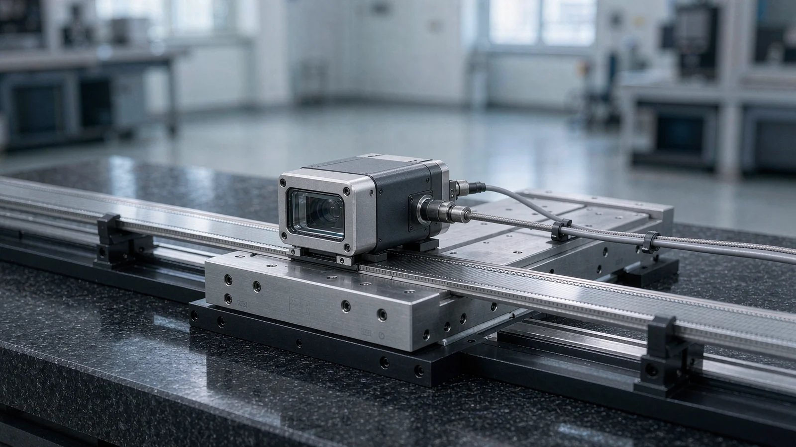
An incremental optical encoder produces two sinusoidal or square-wave channels, A and B, in quadrature: counting their edges yields displacement with direction, but nothing in the count says where the axis is. The index pulse—labeled Z on many drives, I0 in manufacturer documentation, or one-per-rev on rotary encoders—closes that gap. On a rotary encoder it occurs exactly once per mechanical revolution; on a linear optical encoder it is produced by a reference mark on the scale, a track whose geometry places its output pulse at one fixed location per scale cycle pattern. The defining property is registration: the index edge occurs at a manufacturer-specified state of the A and B channels, so the combination of 'index arrived' and 'which A/B state was active' identifies one unique point within the signal period.
Two datasheet terms describe that registration. The gating convention states which A/B state qualifies the index—for example, the index is valid while A is high and B is low—and the width specification states how long the index pulse lasts, in electrical degrees of the signal period or in linear units on a linear scale. An ungated index pulse whose width is narrower than one quadrature state leaves an ambiguity the gating is meant to remove: two identical index pulses within one period can be distinguished only by checking the A/B state at the index edge. Precision-stage work should treat the index not as an independent third signal but as a qualifier that makes one particular A/B state mechanically unique. This is also why index quality cannot be evaluated on the index channel alone—the A/B channels it gates are part of the specification.
Index width, tolerance, and the validity window
Index width is specified in electrical degrees (commonly 90, 180, or 360 degrees of the signal period) or, on linear encoders, as a length on the scale. The critical engineering consequence comes from converting width to time. A rotary encoder producing its signal at frequency f delivers a 90-degree index pulse lasting only 0.25/f seconds—at a 100 kHz signal frequency that is 2.5 microseconds, and at 1 MHz it is 250 nanoseconds. A controller that polls the index input at a soft scan rate can simply miss the pulse at operating speed. Homing implementations therefore either slow the axis until the index is comfortably wider than the sampling interval, or use hardware latching, which responds to the edge rather than to a sampled level.
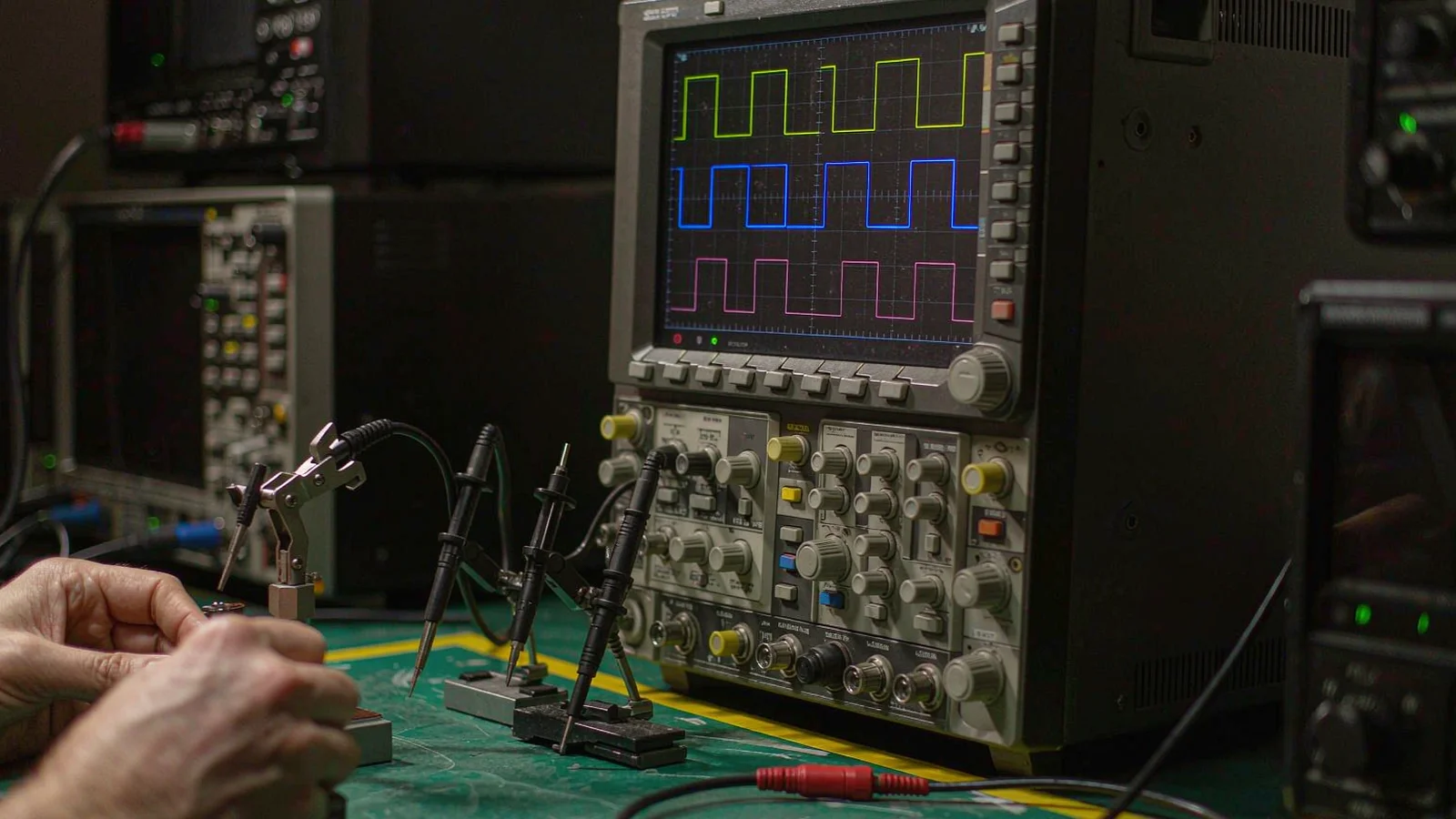
Width also carries a manufacturing tolerance, and the gating adds a third constraint: the A/B state is only a valid qualifier inside the window where the index is guaranteed to overlap it. If the index sits near a quadrature transition and its width tolerance lets it shift toward that transition, a fraction of units in a population could see the qualifying state change within the pulse. Responsible datasheets specify the width such that the qualifying state is stable across the full tolerance band, but the integrator should verify this on the actual installed encoder—an oscilloscope capture of A, B, and index at the homing speed, with the pulse width measured in time and the A/B state checked for stability across the entire pulse, is the ten-minute test that prevents an intermittent, speed-dependent homing failure from ever reaching the field. Contamination or signal-level drift that shifts the index threshold crossing also narrows the effective pulse, which is one more reason the margin between pulse width and sampling interval should not be consumed by design.
Homing and zero referencing on precision stages
Homing with an index follows one of three standard shapes. Index-only search drives the axis at low speed until the index edge appears and sets zero there—simple, but its repeatability is set by the search velocity and the deceleration after the trigger, because the axis must stop from the speed it was moving when the pulse arrived. Limit-switch-gated homing uses a proximity or limit switch only to define a home region, reverses at a controlled low velocity, and takes the next index pulse as the datum; the switch's mechanical scatter is removed from the datum path, and only its gating role remains. Index-on-the-fly homing crosses the index at constant velocity and captures position with hardware latching, giving the shortest cycle and the best repeatability. Which shape fits depends on the axis requirement: a handling axis may tolerate index-only, while a lithography stage that must reconstruct its coordinate frame after every power cycle will justify the latch hardware.
Whatever the shape, three implementation choices dominate the achieved repeatability, and all three belong in the homing specification rather than being left to the firmware default. First, direction of approach: the index edge triggers on one slope, and approaching from the opposite side shifts the trigger point by any asymmetry in the signal thresholds, so the direction must be fixed and never reversed between commissioning and production. Second, search velocity: trigger latency in the sensing chain converts velocity into position error—one microsecond of total latency at 10 mm/s is 10 nanometers, at 100 mm/s it is one micrometer. Third, settle behavior: what matters for the machine datum is not where the trigger occurred but where the axis finally rests after the homing move, so the sequence should decelerate, settle, and then define zero either from the latched value corrected by the known travel, or from a re-read at rest. Datum placement strategy—where in the travel the zero is placed relative to the index and how limits are derived from it—is a system-level decision covered in dedicated reference-mark datum planning.
Index-on-the-fly latching with the A/B channel state
Index-on-the-fly operation treats the index edge as a sampling command. When the index crosses its active edge at constant axis velocity, capture logic simultaneously latches the instantaneous A/B channel state and the current interpolation counter value. Because the encoder's gating convention guarantees that this A/B state corresponds to exactly one position within the signal period, the latched combination—index event plus A/B state plus counter remainder—reconstructs a position that is unique to the finest interpolated resolution, not merely to the signal period. The controller then computes the machine zero as the index position plus the measured offset implied by the latched state. The axis never has to stop or reverse to find the index precisely, which is why this method dominates in exposure, wafer, and metrology stages where homing time is charged against throughput.
The latch path is where the error sources concentrate, and each has a specification. Propagation delay asymmetry: the index and A/B signals travel different routes through the encoder's electronics and the receiver chain, so an edge that is simultaneous at the encoder arrives at the latch separated by tens to hundreds of nanoseconds; multiplied by axis velocity, that delay converts directly into a position offset, which is tolerable only because it is stable and therefore absorbed into the calibration of zero. Trigger jitter: noise and threshold uncertainty on the index edge vary the latching instant run to run, and unlike a fixed delay, jitter appears as scatter that sets a floor under homing repeatability. Sampling coherence: if the A/B state and the counter value are latched by different hardware events rather than one, the two samples can straddle a quadrature edge and the reconstructed position lands one count off. The remedy is architectural—single-point capture of index, A/B, and counter by the same strobe—and its verification is empirical, homing repeatedly at production speed and measuring the scatter of the reconstructed zero.
A defensible homing repeatability budget names its terms. Index width tolerance contributes only if the sampling margin is thin—when pulse width in time approaches the latch or polling interval, the trigger point moves with the tolerance band. Propagation delay asymmetry contributes a fixed offset, not scatter, and belongs in the accuracy of the datum rather than its repeatability, provided delay does not change with temperature. Trigger jitter contributes scatter directly: RMS jitter in seconds times axis velocity in millimeters per second gives an RMS position scatter in nanometers. Approach velocity multiplies every time-based term, which is why homing sequences that need nanometer-class repeatability home slowly or rely on hardware latching and treat residual velocity effects in calibration. Mechanical settle contributes what the deceleration profile and stage friction leave behind, typically dominating all electrical terms on a direct-drive stage unless the sequence includes a defined settle time. Finally, if a switch gates the search, its repeatability appears only in where the slow reverse segment starts—not in the datum itself, which is the index—so a poor switch costs cycle time, not accuracy.
A practical budget for a switch-gated, index-datumed homing sequence on a precision linear stage illustrates the arithmetic. With a 20-micrometer signal pitch interpolated to 1 nanometer, a 180-degree index width gives a 10-micrometer pulse; at the 5 mm/s homing speed the pulse lasts 2 milliseconds, vastly wider than the latch response, so width tolerance is a non-issue. Trigger jitter of 100 nanoseconds RMS contributes 0.5 nanometers. Delay asymmetry of 200 nanoseconds contributes a 1-micrometer offset that calibration absorbs. Mechanical settle after the homing move, if the sequence allows 200 milliseconds and the stage is direct drive, contributes a few nanometers of residual drift; without the settle time it can contribute micrometers. The combined repeatability lands in the low nanometers only when every term, especially settle, is actually controlled—the budget's job is to show which term is currently the largest and therefore worth engineering next.
Capture A, B, and index on an oscilloscope at homing speed; measure index width in time and confirm the A/B state is stable across the full pulse
Fix the homing approach direction and search velocity in the machine parameters; never change either after the datum is calibrated
Latch index, A/B state, and interpolation counter with one hardware strobe—no software polling in the capture path
Measure propagation delay asymmetry once, treat it as a fixed datum offset, and absorb it into calibration
Include a defined settle time after the homing move; verify final repeatability over at least 20 re-home cycles
Re-check index pulse width after cleaning or readhead gain adjustment—threshold shifts narrow the effective pulse
The index pulse gives an incremental optical encoder the one thing its A/B channels cannot supply: a repeatable mechanical datum. But the datum is only as good as the implementation around it. The width and tolerance of the pulse determine whether it can even be caught at homing speed; the gating relationship to the A/B state is what makes the index position unique within the signal period; and the latch chain—propagation delay, trigger jitter, sampling coherence—decides how much of the encoder's resolution survives into the reconstructed zero.
The working discipline is consistent across homing strategies: read the index specification as a system of width, tolerance, and gating rather than as a single pulse; verify it on an oscilloscope at the actual homing speed; fix approach direction, velocity, and settle behavior in writing; latch with hardware, not software polling; and close the loop with a measured repeatability budget compared against the axis requirement. Executed this way, index-based homing delivers a machine zero that repeats to a few nanometers on a precision stage—and, just as importantly, fails in documented, diagnosable ways when one of the budget terms is disturbed.
Datasheet extract for the installed encoder showing index pulse width, width tolerance, gating state relative to A/B, and index rise/fall times
Oscilloscope capture of A, B, and index channels at operating homing speed, confirming pulse width in time and stable A/B state across the index
Homing sequence documentation stating search direction, search velocity, latch mechanism, and the reconstructed zero position convention
Repeatability test record: at least 20 re-home cycles with the settle position recorded each time, plus the scatter statistic used
Homing repeatability budget listing each error contribution and its magnitude, with the combined value compared against the axis requirement
FAQ
Questions engineers ask before selection.
What is the difference between the index pulse and a reference mark?
On a rotary encoder, the index (Z, I0, one-per-rev) is produced once per mechanical revolution by a dedicated track on the code disc. On a linear encoder, the equivalent feature is usually called a reference mark: a physical structure on the scale whose pulse occurs at one fixed location. Functionally they are the same—a single output edge registered to a known A/B state—so the homing, latching, and budgeting principles in this guide apply to both. Some linear scales carry multiple reference marks with defined spacing, which shortens the search travel but does not change the latch and error-source analysis.
Why does the A/B channel state at the index edge matter?
The index pulse alone identifies a location only within one signal period; it does not say where in the period the axis sits. The gating convention—typically a defined combination of A and B levels—ties the index edge to exactly one state of the quadrature signals, and that state corresponds to one unique position within the period. Capturing the A/B state simultaneously with the index event is therefore what upgrades the datum from signal-period accuracy to interpolated-resolution accuracy. If the A/B state is sampled outside the guaranteed validity window, two homing runs can differ by a full signal period.
How fast can I home on the index pulse?
The limit is set by index width in time versus the response of your capture path. Convert width to time: a 90-degree index at a signal frequency f lasts 0.25/f. If that pulse is not substantially wider than the controller's polling interval plus its response time, the index will be missed or triggered inconsistently. Either reduce the homing velocity until the margin is comfortable—typically at least a factor of ten—or use hardware edge latching, which does not depend on pulse duration. Remember that velocity also multiplies trigger latency and jitter into position error, so faster homing costs repeatability even when the pulse is captured reliably.
Why is my homing repeatability worse than the encoder's specification?
The encoder datasheet characterizes the index signal, not the homing sequence. The gap usually comes from terms the sequence adds: search velocity multiplying trigger latency and jitter, mechanical settle-out after the homing move, software polling instead of hardware latching, an approach direction that changed between calibration and production, or a gating switch that was assumed to be the datum. Build an explicit budget—jitter times velocity, delay asymmetry, width tolerance margin, settle drift—measure each term, and the dominant contributor usually becomes obvious immediately.
Does an absolute encoder eliminate the need for homing?
It eliminates the search: an absolute encoder reports position within its travel immediately at power-up, so no index crossing is required to establish a coordinate frame. The machine still needs a defined startup validation, a strategy for limit and datum consistency, and—for multi-turn or travel-beyond-single-word applications—its own reference logic. Many precision machines therefore keep both: an absolute interface for fast startup and recovery, and the index or reference mark as an independent physical datum for calibration and verification. The two serve different roles and are not interchangeable.