
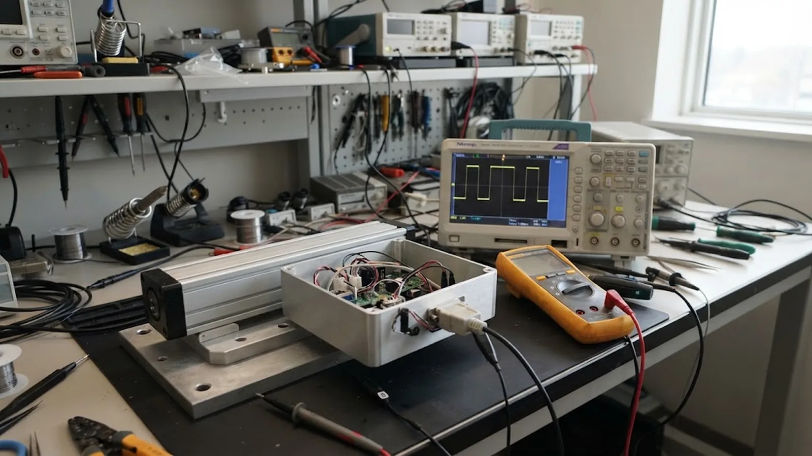
Three-channel oscilloscope access
Simultaneous view of A, B and Z at the controller input is the minimum; differential probes or math subtraction for RS-422 pairs reveal faults single-ended views hide.
TECHNOLOGY / ENCODER INTERFACES
A, B and Z signals carry all position information an incremental encoder has, and most field failures live in their timing, level or wiring. This guide gives a systematic procedure for diagnosing ABZ faults—counting errors, missed index pulses, direction confusion—using an oscilloscope and a multimeter.
Published
DIRECT ANSWER
Most ABZ faults fall into five families: nothing at all (power, wiring, driver failure), counting errors only at speed (signal level marginal, edge filtering, cable capacitance), direction-dependent errors (A and B swapped, or one channel damaged, breaking quadrature), index problems (Z missing, wrong width, or mistriggered by noise because its edge is used without qualification by A and B), and intermittent faults under motion (flexing cable, connector contact, EMC). A systematic diagnosis separates these families first with static checks—power, termination, DC levels—then with a three-channel oscilloscope view of A, B and Z together, which exposes timing relationships no multimeter can show.
The key discipline is to compare what the signals should look like against the datasheet, not against memory: quadrature phase of 90 degrees plus or minus a stated tolerance, Z pulse width in electrical degrees, differential RS-422 levels with the specified termination, and edge rates consistent with the driver type. Deviation from any of these points to a specific cause—swapped pairs, lost differential mate, marginal amplitude, noise on the index—and each has a distinct remedy.
ENGINEERING CONTEXT
When an incremental encoder axis misbehaves, symptoms arrive flattened by the controller: 'position drifts', 'it loses home', 'direction is backwards'. Technicians swap the encoder, and the fault moves or vanishes, leaving no conclusion—the cable, the controller input and the encoder are all suspects. Time is then lost on trial-and-error replacements because nobody looked at the signals themselves. ABZ troubleshooting is quick and conclusive when done in the right order: the interface is slow square waves, visible on any three-channel scope, and the datasheet defines exactly what correct looks like. The procedure below turns a guessing game into a half-hour diagnostic.
Discuss your requirement ↗CRITICAL REQUIREMENTS
Simultaneous view of A, B and Z at the controller input is the minimum; differential probes or math subtraction for RS-422 pairs reveal faults single-ended views hide.
Signal type (TTL, open collector, line driver), termination requirement, Z pulse width, quadrature tolerance and minimum edge rates—all acceptance criteria come from this document.
Jog mode or hand rotation at constant slow speed, so timing relationships can be observed without speed-dependent effects masking the basics.
Ability to measure each differential pair separately, and to disconnect the controller input, so the encoder side and the receiver side can be tested independently.
BUYER MATRIX
Give every shortlisted supplier the same process definition and request configuration-specific proof.
| Symptom | Likely family | Scope signature | First checks |
|---|---|---|---|
| No counts at all | Power, wiring, driver | No transitions on any channel | Supply voltage at connector, cable continuity, fuse and input configuration |
| Lost counts at speed only | Signal integrity | Rounded edges, undershoot, amplitude decay at frequency | Termination fitted, cable length vs driver rating, edge rate at speed |
| Direction reversed or half counts | Wiring / quadrature | A and B not 90 degrees apart, or channels swapped | A-B pair assignment against datasheet, quadrature phase measurement |
| Homing inconsistent | Index | Z absent, too narrow, or noisy | Z pulse width in electrical degrees, Z qualification by A and B in controller |
| Faults appear only in motion | Cable / EMC | Glitches correlated with flexing or with drive switching | Cable flex test with scope attached, shield bonding, separation from motor cables |
Before touching a scope knob, verify the supply at the encoder connector with the cable installed and the encoder running: voltage drop across a long cable or a tired connector is the most common cause of marginal signal levels. Measure each signal's DC state where the encoder idles—differential outputs should show a valid logic level across each pair, and open-collector outputs need the controller's pull-up to show anything at all. Confirm the termination: RS-422 pairs want their characteristic-impedance termination at the receiver end; missing termination shows up later as rounded, ringing edges at speed, while termination where the datasheet forbids it overloads the driver.
These static checks eliminate half the fault families in minutes and, just as importantly, establish which half remains. If supply, continuity and levels are all correct, the fault is in timing, noise or mechanics—and the oscilloscope becomes the tool that decides.
Trigger on A and display all three channels with the axis jogging slowly and steadily. Read four things in order. First, quadrature: B should lag or lead A by a quarter of the signal period, consistently in both directions; a phase error near 90 degrees that varies with position points to mechanical alignment, while a fixed wrong phase points to wiring or a damaged channel. Second, symmetry: high and low times of each channel should be equal; asymmetry indicates signal integrity problems or, on analog-derived interfaces, amplitude imbalance. Third, the index: Z should appear once per scale period, with the datasheet width, and always at the same phase relationship to A and B. Fourth, cleanliness: any glitch on Z between its legitimate pulses is a homing failure waiting to happen.
Direction confusion deserves its own note: if the axis counts backwards, either A and B are swapped at the controller, or the phase convention differs from what the controller expects. Swapping one pair—or configuring the controller's count direction—is the fix; reversing both wires of both channels changes nothing, since that only inverts each logical level.
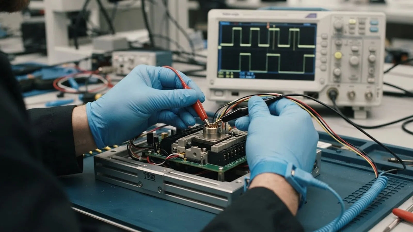
The Z channel fails in characteristic ways. Its pulse can be narrow—a few electrical degrees—so marginal cabling or a slow receiver edge easily erases it; check the width specification and measure it, do not assume it. It can be mistriggered: noise on Z at the moment the controller samples produces spurious home positions, which is why well-designed homing routines qualify the Z edge with the state of A and B rather than trusting Z alone. And it can be consumed by configuration: some controllers expect one index per revolution, others per encoder cycle, and a mismatch between the encoder's reference mark spacing and the controller's expectation looks exactly like a missing index.
When homing is inconsistent, the procedure is to capture Z with A and B displayed, count Z pulses per travel unit against the expected datum spacing, and then check how the controller qualifies the edge. In most cases the encoder is innocent—the fault is in width, noise or configuration—and the scope proves it in one capture.
If the encoder is perfect on the bench and faulty in the machine, the remaining suspects are the cable and the environment. Flex the cable by hand at various points while watching the signals on the scope—a dropping channel is an internal conductor fracture, often within centimetres of a connector boot. Watch for glitches synchronized with drive switching or with contactor operation: that is EMC coupling, and the remedy is shielding, grounding and cable separation, not a different encoder. Check that the shield is bonded at the correct end per the interface specification and that encoder cabling does not share a tray or drag-chain compartment with motor power lines.
Document the reproduction conditions before changing any hardware: speed, direction, cable position, nearby equipment. A fault that reproduces predictably is a fault that can be fixed once; a fault chased by parts-swapping without conditions recorded tends to return with the next vibration or the next summer heat.
CONCLUSION
ABZ troubleshooting rewards order: static electrical checks first, then the three-channel timing view, then motion and environment. Each step eliminates a fault family, and the datasheet supplies the acceptance values—quadrature phase, Z width, termination, edge rates—that turn observation into verdicts.
Keep a scope capture and the reproduction conditions in the record for every resolved fault. The next intermittent problem then starts from evidence instead of from parts swapping, and the half-hour diagnostic stays a half hour.
SOLUTION ROUTES
EVIDENCE CHECKLIST
FAQ
Typically signal integrity: unterminated RS-422 pairs, excessive cable capacitance for the driver, or marginal supply voltage. Edges degrade with frequency until the receiver misses transitions. Check termination, cable length against the driver rating and edge quality on the scope at operating speed.
Swap one differential pair—A with its complement, or B with its complement—or change the controller's count-direction configuration. Swapping both pairs only inverts logic levels and leaves the direction unchanged.
Z is the index or reference mark, once per encoder or scale period. Homing fails when the pulse is too narrow to survive the cabling, when noise creates false Z edges, or when the controller's index configuration does not match the encoder's datum spacing. Reliable homing qualifies the Z edge with A and B states.
For differential line-driver interfaces such as RS-422, yes—the receiver end needs the termination the datasheet specifies. Missing termination causes rounded, ringing edges that fail at speed; incorrect termination can overload the driver and reduce amplitude.
Suspect the cable and environment. Flex the cable while watching the signals for a dropping channel, look for glitches correlated with drive switching, and verify shield bonding and separation from power cables. Record the exact reproduction conditions before replacing any hardware.
AUTHORITATIVE SOURCES
TECHNICAL REVIEW
Send the application, critical parameters and any drawing or process information available.
Discuss your application ↗