
Diagnostic coverage
Know which conditions the encoder monitors—signal amplitude, reference marks, position validity, communication integrity—and which it does not.
TECHNOLOGY / ENCODER RELIABILITY
How modern optical encoders monitor signal health, how warning and fault states are reported through alarm outputs and bidirectional interfaces, and how to wire a response strategy into the machine.
Published
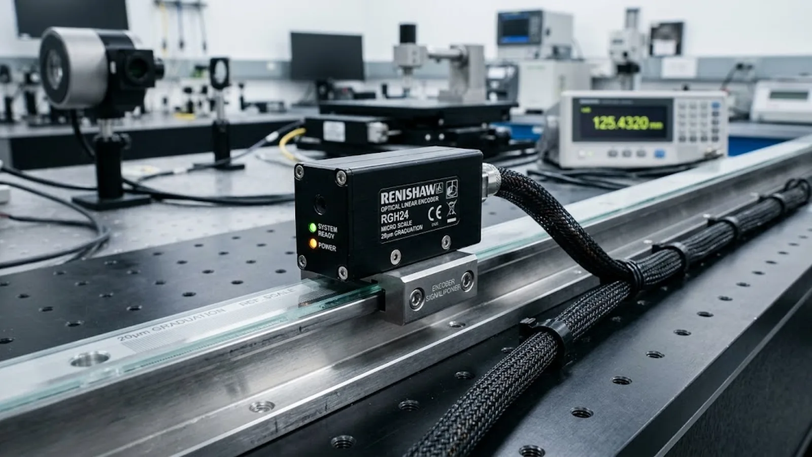
DIRECT ANSWER
Encoder diagnostics are the monitoring functions built into a position feedback system that continuously check whether the measured position can still be trusted. Depending on the encoder family, this includes signal amplitude monitoring of the scanning signals, plausibility checks on the absolute position word, reference-mark and limit monitoring, and error-detection codes on the serial data stream. The results are reported in two forms: a dedicated alarm or warning output that switches state directly, and status or diagnostic words that are transmitted cyclically over a bidirectional interface such as EnDat 2.2 or BiSS-C.
Most encoder suppliers distinguish a warning state, where scanning quality has degraded but the position value is still within its valid tolerance, from a fault state, where the position data must no longer be used. The value of diagnostics depends entirely on the machine side: the alarm line must be wired to an input the controller actually evaluates, and each alarm class needs a defined response—controlled stop, part marking, or maintenance logging—otherwise a degraded scale is discovered only when scrap or downtime reveals it.
ENGINEERING CONTEXT
An optical encoder rarely fails without notice. Contamination on the scale, an aging LED in the illuminator, a drifting readhead gap or a damaged cable segment all degrade the scanning signals gradually, and the position value keeps updating as if nothing were wrong. The machine converts this silent degradation into dimensional drift, unplanned stops or scrapped workpieces. Most modern encoders already provide the early indication through diagnostics—the missing piece in many installations is that the alarm output is left unconnected, the interface status words are not evaluated, and no response is defined for the states the encoder reports.
Discuss your requirement ↗CRITICAL REQUIREMENTS
Know which conditions the encoder monitors—signal amplitude, reference marks, position validity, communication integrity—and which it does not.
A dedicated alarm/warning output or a bidirectional interface whose status words are read and evaluated by the controller.
Defined controller behavior per alarm class: controlled stop, axis disabling, workpiece marking or maintenance logging.
The worst-case time from fault occurrence to report must fit the machine's danger and scrap window, documented by the supplier.
BUYER MATRIX
Give every shortlisted supplier the same process definition and request configuration-specific proof.
| Aspect | Dedicated alarm output | Interface status/diagnostic words | External monitoring |
|---|---|---|---|
| What is reported | Warning and fault states as switched signals | Cyclically transmitted status, diagnostic and alarm data | Whatever an external sensor infers indirectly |
| Granularity | Two or three discrete states | Detailed per-condition flags and error counters | Inferred from drift, temperature or downtime events |
| Reaction time | Fast, limited only by controller input scan | One transmission cycle of the interface | Slow; depends on inspection intervals |
| Wiring effort | One input per encoder plus evaluation logic | Already present on EnDat 2.2 / BiSS-C cabling | Additional sensors and evaluation hardware |
| Typical use | Hard-wired safety of position on critical axes | Predictive maintenance and detailed fault analysis | Legacy axes without native diagnostics |
Diagnostics in an optical encoder watch the conditions that determine whether the position value is valid. The most fundamental is the amplitude and quality of the scanning signals: as contamination films the scale or the LED output fades, the signal swings shrink and the interpolation of the position value becomes unreliable. Electronics monitor these swings and compare them against limits at which the position can no longer be guaranteed to specification.
Beyond signal health, encoders check the integrity of the data itself. Absolute position words carry check sums or cyclic redundancy checks, so a transmission or memory error is detected instead of silently accepted. Reference-mark and distance-coded evaluations report whether a valid reference datum has been captured, and limit switches or commutation tracks report their own validity. Bidirectional interfaces such as EnDat 2.2 and BiSS-C add a structured diagnostic channel: the readhead transmits status bits, alarm and warning codes, and in many families additional values such as operating temperature or operating hours alongside the position.
The boundary matters as much as the coverage. Diagnostics observe the encoder and its immediate connection; they do not observe the mechanical mounting, the Abbe offset or the thermal behavior of the stage. A passing diagnostic state means the feedback is healthy, not that the machine is accurate.
Encoder suppliers typically grade their diagnostic output into two classes. A warning indicates that a monitored condition is approaching or has crossed a first threshold—signal amplitude drifting downward, temperature leaving the nominal range—while the position value is still valid and the axis can continue to operate in a controlled way. A fault indicates that the position data must no longer be used: the controller should treat the axis as without feedback, ramp down under whatever fallback exists, and disable torque in a defined manner.
This distinction is the foundation of a sensible response strategy. Treating every alarm as an emergency stop wastes availability; treating warnings as noise wastes the early indication they provide. The useful middle ground is a graded response: on warning, mark the current part for inspection, log the event and schedule maintenance; on fault, bring the axis to a controlled stop and prevent further motion until the cause is cleared.
A diagnostic function is only as useful as the time it needs to report. Suppliers document the worst-case interval between the occurrence of a fault and its appearance on the alarm output or in the interface data, and the controller adds its own input scan and processing time. For a slowly degrading condition such as LED aging, seconds are irrelevant; for a sudden cable break on a fast axis, the total time decides how far the machine coasted without valid position. Ask for the reaction time figure as part of the encoder specification rather than discovering it during commissioning.
The most common integration failure is electrical, not technical: the encoder offers a warning output and the machine never connects it. For incremental encoders with discrete alarm lines, the output belongs on a controller input that the PLC or CNC evaluates in logic—latching the event, stopping motion and presenting a message to the operator, not just lighting a panel lamp that nobody monitors.
With bidirectional serial interfaces, the diagnostic channel is already in the cable. EnDat 2.2 transmits status and diagnostic data that the drive or control can evaluate cycle by cycle; BiSS-C provides status and error bits within the telegram. Machine builders should make the evaluation explicit in the drive configuration: define which status combinations map to warning handling and which to fault handling, and test each class during commissioning by deliberately triggering the condition on a spare axis where possible.
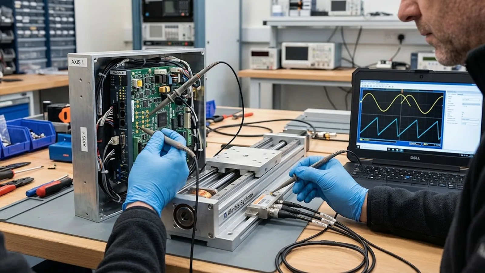
Diagnostics become economically interesting when the reported states drive maintenance instead of emergencies. Because the leading degradation mechanisms—scale contamination, illuminator aging, gap drift—develop over weeks rather than milliseconds, warning data logged over time shows the direction of travel. A signal amplitude that declines steadily across a quarter indicates a cleaning or replacement decision that can be scheduled into planned downtime.
A practical scheme records, for each axis: the alarm class, the timestamp, the axis state at the time and the production context. Alarms that correlate with specific conditions—a warning appearing only during cold starts, or after a particular guard is opened—localize the cause faster than a breakdown ticket. Axis families with the same duty can be compared, and encoders that warn repeatedly before failure justify a stocking decision for spares.
The strategy should also state what diagnostics do not cover. Periodic verification of accuracy—error mapping against a reference—remains necessary because compensation-relevant drift does not necessarily trip a diagnostic threshold. Diagnostics protect position validity; they do not replace metrology.
SENFU treats diagnostics as part of the feedback specification, not an optional feature. For stage and machine projects, the useful conversation covers which monitored conditions the configured encoder family reports, whether the machine control consumes the alarm line or the interface status words, and what response behavior is expected per class. These points can be settled at selection time so the diagnostics arrive already integrated.
On the supplier side, the relevant evidence is concrete: which conditions are monitored, the warning and fault thresholds relative to specification, the worst-case reporting time, and the diagnostic data available over the configured interface. Ask for these as configuration-specific statements, because diagnostic scope differs between encoder families and interface options.
Submit the axis and machine control description through the application form and SENFU can review the diagnostic integration together with the encoder configuration, including the wiring and evaluation points to be defined before commissioning.
CONCLUSION
Optical encoders monitor their own health—scanning signal quality, data integrity, reference validity—and report degradation through alarm outputs and interface diagnostic data long before position errors appear on the workpiece. The monitoring is standard on modern families; the integration is what varies between machines.
Connect the report path, evaluate it in the controller, and give each alarm class a defined response from logging to controlled stop. Combined with periodic accuracy verification, which diagnostics do not replace, this turns encoder degradation from an unplanned event into scheduled maintenance.
EVIDENCE CHECKLIST
FAQ
A warning signals that a monitored condition has degraded but the position value is still valid within tolerance, so controlled operation can continue. A fault signals that the position data must no longer be used and the controller should stop the axis under its defined fallback behavior.
Through two channels: discrete alarm and warning outputs that switch state directly, and status or diagnostic words transmitted cyclically over bidirectional interfaces such as EnDat 2.2 or BiSS-C. The discrete line offers the fastest independent path; the interface offers detail for analysis.
Contamination on the scale reduces the scanning signal amplitude, and most encoders monitor amplitude against warning and fault thresholds. Detection depends on the contamination density crossing the threshold; a light film may affect accuracy within specification before a warning triggers, which is why periodic accuracy checks remain necessary.
The interface carries the same information in detail, but the discrete alarm output provides an independent, fast path that survives interface-level failures. For axes where loss of position is critical, evaluating both is the conservative choice; for others, the interface channel with a defined response may suffice.
A common scheme: on warning, mark or inspect the current part, log the event and schedule maintenance; on fault, execute a controlled stop with the available fallback, disable further motion and require acknowledged clearance before restart. The exact mapping is a machine-level decision that should be defined before commissioning.
Send the encoder family under consideration, the machine control and drive interface, and the intended response per alarm class. SENFU can review which conditions the configuration monitors, the reporting path and the reaction-time figures to be documented before commissioning.
AUTHORITATIVE SOURCES
TECHNICAL REVIEW
Send the application, critical parameters and any drawing or process information available.
Discuss your application ↗