
Update rate matched to the motion profile
Confirm the maximum output frequency for incremental and analogue outputs, or the worst-case serial transaction time for BiSS-C and EnDat, against the fastest speed and the controller input limit.
TECHNOLOGY / ENCODER INTERFACES
Incremental TTL and RS-422 quadrature, analogue 1 Vpp sin/cos, BiSS-C and EnDat 2.2 all carry the same position information over very different electrical paths. This guide compares data rate, latency, diagnostics, wiring and controller compatibility so an interface can be chosen against a real motion requirement.
Published

DIRECT ANSWER
The four families differ in where interpolation happens and in how much diagnosis travels back with the position. Incremental TTL or RS-422 quadrature and analogue 1 Vpp sin/cos hand the controller a raw, essentially continuous signal that it counts or interpolates, so latency is minimal and diagnostics are thin. BiSS-C and EnDat 2.2 hand over an absolute position word inside a deterministic serial frame, at the cost of a transaction delay of a few microseconds, a clock rate that trades against cable length, and a controller that must implement the protocol properly. Choose incremental when the drive already counts quadrature well and a homing routine is acceptable; choose analogue when the interpolator lives in the drive; choose BiSS-C or EnDat when the axis needs absolute recovery, register-level diagnostics or parameter memory the controller can read.
The decision closes on four numbers, not on a protocol name: the update rate the controller can accept at the required speed, the total loop delay the servo bandwidth can tolerate, the diagnostic content the machine will actually use, and the wiring the mechanical design can carry. Before ordering, confirm the controller supports the exact protocol version and frame length, confirm the clock rate the specified cable length allows, and require the frame definition, delay budget and error reaction in the order documentation so the interface can be verified at commissioning.
ENGINEERING CONTEXT
Interface selection is usually inherited rather than made. A machine builder picks the encoder family first, then discovers that the drive only counts quadrature, or that the serial clock rate the cable length permits leaves too little margin in a high-bandwidth loop, or that the absolute encoder arrived with a frame the controller parses into the wrong resolution. Each of these is a wiring or configuration problem that becomes a schedule problem, because the cure is a different encoder variant, a different interface card or a cable redesign. The reverse failure is just as common: a bidirectional protocol chosen for its diagnostics on an axis where the servo needs continuous feedback, adding transaction delay and a sampling artefact to a loop that was already tight.
Discuss your requirement ↗CRITICAL REQUIREMENTS
Confirm the maximum output frequency for incremental and analogue outputs, or the worst-case serial transaction time for BiSS-C and EnDat, against the fastest speed and the controller input limit.
Add encoder transaction or propagation delay to sampling, filtering and drive transport delay, and check the total against the phase margin available at the target bandwidth.
Decide whether the axis needs CRC-protected status, warning and alarm bits, encoder memory and parameter access, or whether a homing routine and periodic accuracy checks are sufficient.
Check core count, differential pairs, termination, shielding and separation from motor power, and confirm the drive implements the exact protocol version, frame length and error reaction.
BUYER MATRIX
Give every shortlisted supplier the same process definition and request configuration-specific proof.
| Interface | What travels on the cable | Update rate and latency | Diagnostics | Typical fit |
|---|---|---|---|---|
| Incremental TTL | Single-ended A, B and Z pulses at logic level, counted as quadrature in the controller | Continuous pulse train, latency is essentially propagation plus counter input delay; limited by cable length, edge quality and counter input frequency | Almost none; position is lost at power down and signal loss looks like missing counts | Short cables, simple axes, controllers with a good quadrature counter and an acceptable homing routine |
| Incremental RS-422 | Differential A+/A-, B+/B- and Z+/Z- pairs driven by a line driver and received differentially | Same continuous behaviour as TTL with much better noise immunity; maximum frequency set by receiver, cable capacitance and counter input | None beyond pulse presence; some encoders add an alarm line or a level output | Industrial axes, longer cable runs, electrically noisy cabinets |
| Analogue 1 Vpp sin/cos | Differential sine and cosine at nominally 1 V peak-to-peak per signal period, plus a once-per-period reference pulse | Continuous; the interpolator in the drive produces position with only analogue propagation and conversion delay, the lowest-latency high-resolution route | No protocol-level diagnostics; signal degradation appears directly as subdivision error and must be found with a Lissajous check | High-bandwidth servo loops, drives with their own interpolation, fine resolution at high speed |
| BiSS-C | Controller-driven clock pair and a returning data pair; unidirectional frames carry position, status and CRC, bidirectional mode allows register and parameter access | Deterministic cycle time: frame bits divided by clock rate, plus slave processing time and two line delays; clock rate trades against cable length | Warning and error bits, CRC over the frame, register access for configuration and identification, safety-oriented variants exist | Absolute position at power-up, open licence-free integration, controller or FPGA implementations |
| EnDat 2.2 | Bidirectional serial clock and data pair, optionally accompanied by additional incremental sin/cos signals | Deterministic transaction with delay compensation; clock rates run from hundreds of kilohertz to several megahertz depending on device generation and cable length | Alarms and warnings, checksum protection, a memory area for encoder parameters and additional information such as temperature or acceleration sensing | Absolute feedback on drives with established EnDat support, axes that need parameter memory and structured diagnostics |
The optical side of an encoder produces one signal period per scale pitch, and something has to divide that period into usable counts. The division happens either inside the readhead, which then emits digital counts or an absolute position frame, or inside the drive, which receives the raw periodic signal and interpolates it. That single architectural decision sets the wiring, the latency, the failure modes and the diagnostic content of the whole axis.
When interpolation is inside the encoder, position arrives as a word at a defined update rate, and the encoder can also report status, warnings, identification and parameter memory. When it is outside, feedback is continuous and effectively delay-free, but the controller owns signal conditioning, and any degradation in amplitude, offset or phase quadrature becomes subdivision error with no alarm to announce it.
An incremental encoder emits two quadrature channels and a reference pulse, and the controller counts four edges per cycle. Single-ended TTL at logic level is simple and cheap but has limited noise immunity and short reach. RS-422 differential signalling, driven by a line driver and terminated at a differential receiver, is the industrial default: the same information survives cable capacitance, ground shift and cabinet noise far better, at the cost of a driver and receiver at each end.
The limits are electrical rather than optical. The counter input has a maximum frequency, the cable adds capacitance and edge degradation, and the chosen resolution multiplies the pulse rate at any given speed, which is why the honest specification is a resolution-versus-speed matrix rather than a single figure. Diagnostics are minimal: there is no absolute position, so the axis needs a homing routine, and a degraded channel usually appears as a following-error fault rather than as an encoder alarm.
An analogue interface delivers differential sine and cosine, nominally 1 V peak-to-peak per signal period, with a reference pulse marking a datum within the travel. The drive interpolates those waveforms, commonly by a few hundred to several thousand counts per period, and can do so at very high axis speed because no digital transaction has to complete. Position is therefore available continuously rather than at sampled instants, which is why analogue feedback persists on high-bandwidth loops.
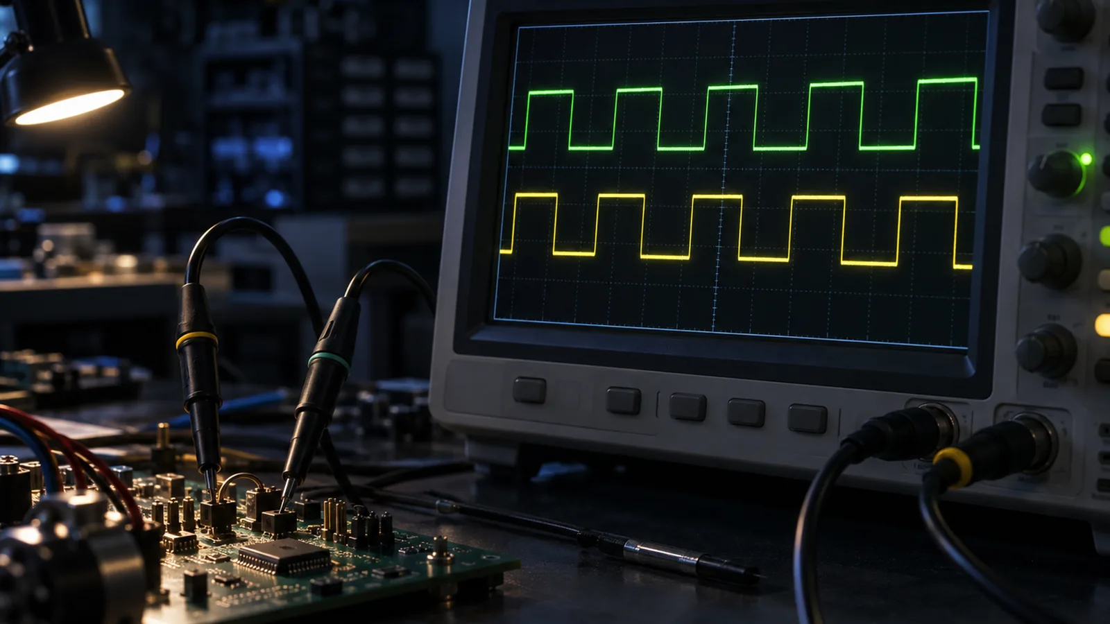
The cost is that signal quality becomes the integrator's responsibility. Amplitude error, DC offset, deviation from quadrature and harmonic distortion convert directly into subdivision error, and nothing in the interface reports it. The Lissajous display is the acceptance instrument: a clean centred circle means a clean signal, amplitude mismatch makes it elliptical, phase error rotates the ellipse, distortion makes it non-circular. Wiring is heavier too: two differential pairs, the reference pair, power and sense conductors.
BiSS-C is an open, licence-free synchronous serial interface maintained by iC-Haus. The controller supplies the clock on one differential pair and the encoder returns data on another. In unidirectional mode the cycle time is constant, with position, status and a CRC protecting the frame. Bidirectional mode also reaches registers and parameters inside the encoder, which is what makes configuration, identification and diagnostic readback possible without a second channel.
Cycle length is computable: frame bits divided by clock rate, plus slave processing time and two line delays. Clock rates up to around 10 MHz are supported on short cables and have to be reduced as the cable grows, so the specification should be read as a clock-versus-length curve rather than as a maximum. Diagnostics are the real argument for BiSS-C on precision axes: warning and error bits and a CRC-protected frame let the controller distinguish a valid position from a suspect one.
EnDat 2.2 is a proprietary bidirectional serial interface from HEIDENHAIN. The controller sends clock and mode commands; the encoder replies with position and can expose a memory area holding parameters, type and serial data, and additional information such as temperature or acceleration sensing. It includes delay compensation and checksum protection, and is available with or without additional incremental sin/cos signals on the same cable.
Licensing is the main commercial difference: the protocol is proprietary and the per-device cost is normally carried by the encoder manufacturer. Controller support is broad among drive vendors that implement it, but the version matters. Confirm the drive supports 2.2 rather than only 2.1, that it parses the frame length and resolution the encoder is configured for, and that it reacts to alarms the way the machine safety concept expects rather than ignoring them.
Serial interfaces cost time, and the amount is negligible on many axes and decisive on others. A frame on the order of fifty bits at a 10 MHz clock is roughly five microseconds before processing and line delay. At a 1 kHz velocity-loop bandwidth that is about two degrees of phase, which is noise; at several kilohertz it is a real slice of phase margin, and it arrives on top of sampling, filtering and drive transport delay. Continuous interfaces remove the transaction term, which is why they persist on the fastest loops.
Core count is the first mechanical constraint: a serial interface needs two pairs plus power, while quadrature and analogue need considerably more, which matters in a tight cable track or on a moving carriage. Serial links are lighter but less forgiving of clock edge quality, termination and shared shielding with motor power. Before ordering, confirm which protocol versions, frame lengths and error reactions the drive implements, check the pinout against the encoder drawing before applying power, and write the version, clock rate, cable length and delay budget into the order so they can be verified at commissioning.
CONCLUSION
Choose the interface from the loop and the machine, not from the catalogue. Incremental quadrature and analogue sin/cos keep latency at a minimum and leave interpolation to the drive, asking the integrator to own signal quality and homing. BiSS-C and EnDat 2.2 return absolute position, status and parameter memory inside a deterministic frame, asking the integrator to budget transaction time and verify controller support. The four numbers that decide it are the same either way: update rate at speed, total delay against available phase margin, diagnostic content the machine will use, and the wiring the design can carry.
EVIDENCE CHECKLIST
FAQ
Both are synchronous serial interfaces returning absolute position over a clock and data pair, with delay compensation and checksum protection. BiSS-C is an open, licence-free specification with unidirectional and bidirectional modes; EnDat 2.2 is proprietary, with a defined memory area, structured alarms and warnings, and optional additional incremental sin/cos signals.
Only if the drive implements both. An analogue input expects continuous sine and cosine and interpolates them; a BiSS-C input expects to supply a clock and parse a frame. Some drives accept both and some accept EnDat with incremental signals, but the supported modes must be confirmed before ordering.
Clock rate, cable capacitance and signal integrity together: the transaction must complete, the clock edge must arrive cleanly and the data must return before the next cycle. Longer runs need a lower clock, so read the specification as a clock-versus-length curve.
The encoder reports absolute position at power-up, which removes the reference search, but the machine still needs a startup validation: confirm the position is valid, confirm travel limits and any multi-turn state, and define the reaction to an alarm. Omitting homing is a machine safety decision, not an encoder feature.
Analogue sin/cos or differential quadrature, because both are continuous and avoid a serial transaction. The encoder is rarely the only delay, though: sampling, filtering and drive transport delay are often larger. Build one delay budget before ruling a digital interface out.
AUTHORITATIVE SOURCES
TECHNICAL REVIEW
Send the application, critical parameters and any drawing or process information available.
Discuss your application ↗