
Deposit exposure declaration
State the environment the scale will face, including oil mist, outgassing sources, coolant splash, resist or process chemistry, and require evidence the encoder was qualified for it.
TECHNOLOGY / ENCODER RELIABILITY
A thin film on an encoder scale rarely stops the axis; it quietly steals optical contrast until interpolation error and jitter drift out of budget. This guide explains where filming comes from, how to read its symptom signature, and which construction and cleaning guarantees to require.
Published
DIRECT ANSWER
Scale contamination is rarely a blockage problem; it is a contrast problem. A film only micrometres thick, whether from outgassed adhesives, oil mist, handling residue or airborne particles, attenuates and scatters the light that should switch cleanly between the grating lands and gaps. The modulated component of the photodiode signals shrinks relative to the DC level, the readhead raises gain to compensate, and interpolation error and position jitter grow while the axis still counts. Progressive films produce a slow drift that mimics ageing; localised deposits produce errors tied to specific travel positions.
Treat contamination as a specification item, not only a maintenance task. Require a declaration of the environments and deposit types the encoder was qualified against, an optical path protected by a sealed window, a lip seal or a laminated scale with wiper, and a cleaning procedure that names compatible solvents and forbids abrasives on the grating. At commissioning, record signal amplitude or a quality index as the baseline, then trend it on a schedule so a falling value triggers investigation before subdivision error leaves the budget the axis was bought to hold.
ENGINEERING CONTEXT
Filming is the most under-specified failure mode in encoder practice because its early symptoms hide inside every other explanation. A falling contrast looks like LED ageing, gain drift or alignment loss, and a position-tied error band looks like a scale defect or a machine geometry problem, so teams replace electronics or realign readheads while the deposit keeps growing. The economics are one-sided: cleaning or replacing a scale costs a maintenance window, while weeks of misdiagnosis cost scrapped parts and a lost production schedule. The difficulty is that few datasheets state what the optical path tolerates, which solvents attack the grating coating, or how signal amplitude should decline before intervention. The fix is contractual rather than heroic: define the deposit exposure the encoder will see, require construction and sealing matched to it, insist on a documented cleaning method, and bind both sides to a measured amplitude baseline recorded at acceptance.
Discuss your requirement ↗CRITICAL REQUIREMENTS
State the environment the scale will face, including oil mist, outgassing sources, coolant splash, resist or process chemistry, and require evidence the encoder was qualified for it.
Require a sealed window, an effective lip seal or a laminated scale with wiper appropriate to the exposure, and ask what each barrier is rated to stop.
Obtain the manufacturer cleaning method in writing: approved solvents, contact rules for the grating, tools and inspection steps, and the conditions that instead require scale replacement.
Record signal amplitude or the readhead quality index at commissioning, and set an advisory and an action threshold so a falling trend triggers cleaning before error leaves budget.
BUYER MATRIX
Give every shortlisted supplier the same process definition and request configuration-specific proof.
| Deposit | Optical effect | Feedback symptom | Mitigation to specify |
|---|---|---|---|
| Oil mist and lubricant film | Broadband attenuation and scattering that lower modulation depth across the full travel | Gradual amplitude decay and rising jitter everywhere on the axis | Lip seal or air purge at the scale aperture, plus amplitude trending in the maintenance plan |
| Outgassed hydrocarbons and adhesives | Progressive transparent filming that shrinks contrast without visible particles | Slow drift misread as LED ageing; gain control masks it until late | Low-outgassing material declaration near the scale and qualification data for the film exposure |
| Airborne dust and fibres | Local shadowing of grating lines where particles lodge on the window or scale | Position-tied error bands and periodic faults at fixed travel points | Positive-pressure purge or sealed window, filtered enclosure air and scheduled inspection |
| Handling fingerprints and residue | Localised smudges that scatter light and upset DC symmetry of the sine and cosine signals | Small offset and quadrature errors after service or installation work | Glove discipline, no-contact rules for the grating and a documented post-handling inspection step |
| Coolant, resist or process splash | Opaque droplets and dried residues that block grating patches outright | Hard counting errors or reference-mark loss in specific travel regions | Physical shielding, process-compatible sealing and a spill-response cleaning procedure |
| Condensation and dried moisture | Haze plus residue rings left after evaporation, often combined with corrosion risk | Contrast loss that varies with humidity and worsens after each wet cycle | Dew-point control, sealing matched to the IP requirement and corrosion-resistant scale coating |
An optical encoder works by turning the scale grating into a light modulator: as the scale moves, alternating lands and gaps chop the illumination so the photodiodes deliver near-sinusoidal signals. The measurement lives in the difference between light and dark, so the quantity that matters is modulation depth, the alternating component relative to the steady DC level. A deposit does not need to cover the grating to matter. A transparent hydrocarbon film only a few hundred nanometres thick changes refractive conditions, attenuates and scatters light, and converts part of the alternating signal into a fixed background level.
The electronics hide the early damage. Automatic gain control raises amplification to keep the internal signal inside its usable window, so the readhead reports healthy while the noise floor climbs with the gain. Because interpolation divides the signal period, absolute offsets and phase imperfections become a larger fraction of a shrinking Lissajous circle, and subdivision error and position jitter grow first, before any accuracy trend appears. A film therefore attacks the axis exactly where the machine feels it least until the process yield suddenly does.
Contamination sources cluster into four families. Chemical films arrive as vapour: outgassed adhesives, cable jackets, greases and elastomers near the scale, plus oil mist from gearboxes, linear guide lubrication and compressed-air exhaust. Particulates arrive in air: dust, fibres, skin flakes and abrasive debris from nearby processes. Process liquids arrive as splash or aerosol: coolants, photoresist, developers and cleaning agents. Finally, contact residues arrive with people: fingerprints and grease transferred during installation or service, which is why many scale failures date precisely to a maintenance intervention.
Each family has a characteristic geometry. Oil-mist and outgassed films deposit slowly and evenly, producing a whole-travel decay that is easy to mistake for ageing. Particulates and splashes localise, producing errors tied to positions that coincide with the deposit, while contact residues cluster around the regions hands reach. Mapping where the machine stores grease, which elastomers sit near the scale aperture, and where technicians touch tells you which defence the specification must emphasise.
Diagnosis discipline separates contamination from its imitators. A uniform, slow decline in signal amplitude over weeks or months points to an even film or an ageing illuminator; the discriminator is time and exposure history, since an LED decays monotonically while a film accelerates in dirty periods. A stationary error band at fixed travel positions points to local deposits, particles or scale damage; scanning the scale under a directed inspection lamp while reading the amplitude profile usually finds the culprit within minutes. Contrast that worsens with humidity or after cold starts suggests condensation residue.
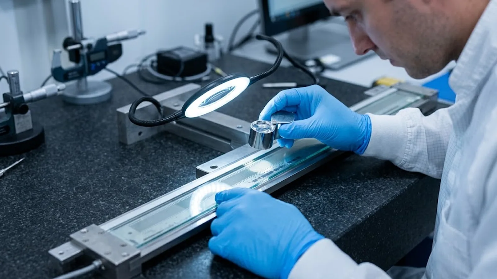
Two precautions prevent self-inflicted damage. First, record amplitude, quality index and error data before cleaning so the before-and-after comparison is objective and so a persistent fault is not masked by a coincidental improvement. Second, never wipe a grating on impulse: dry rubbing drags particles across the structure and can scratch coatings, turning a cleanable film into permanent scale damage. The inspection sequence, the records and the restraint all belong in the written maintenance procedure, not in the memory of whoever happened to be on shift.
The best cleaning strategy is a scale that is never touched. Three construction routes dominate. A sealed optical path places a window between the environment and the grating, so the deposits land on a replaceable or cleanable surface rather than the scale itself, at the cost of one more optical element that can itself film. A lip seal or brush wiper rides on the scale and keeps the measurement zone clear in continuous contact, which suits exposed machine beds but introduces its own wear item. Laminated scales combine the grating with an integrated protective layer that tolerates contact and simplifies wiping.
For oily or dusty atmospheres a positive air purge adds a clean outward flow through the readhead aperture, provided the air is filtered and dried and the exhaust path is designed so particles are not drawn back in. The selection is environmental, not preferential: splash and heavy particulates favour wipers and shields, vapour and mist favour sealed windows and purge, and vacuum machines remove purge from the menu entirely and push the burden onto low-outgassing materials. Ask the supplier which construction their qualification data actually covers rather than accepting a generic contamination statement.

Cleaning is a controlled chemical and mechanical operation, and the grating coating decides what is permitted. The written procedure should name the approved solvents, typically specific spectroscopy-grade alcohols for glass scales, and explicitly forbid the agents that attack coatings, adhesives or the scale substrate. It should specify lint-free wipes, single-stroke technique moving from clean to dirty regions, fresh surfaces between strokes, and the rule that never changes: nothing dry touches the grating, and no hard tool comes near it. For sealed windows the same discipline applies, with the added step of inspecting the window itself for scratches that scattering has caused.
Verification closes the loop. After cleaning, the amplitude or quality index is re-read at the same gap and temperature as the commissioning baseline, and the result is recorded against the date. A value restored to baseline confirms the diagnosis and recalibrates the maintenance interval; a value that stays low means the film etched the coating, a particle remains lodged, or the fault was never contamination.
Four clauses convert this guide into procurement language. Require a deposit exposure declaration covering oil mist, outgassing, particulates and process liquids, with qualification evidence for the concentrations stated. Require the protective construction to be named, window, seal, wiper or laminate, together with its rated exposure limits and service intervals. Require the cleaning procedure as a controlled document, and require that commissioning include a recorded amplitude or quality-index baseline with gap and temperature. Then set advisory and action thresholds with margin against the interpolation error budget, exactly as an illuminator lifetime plan would.
In operation, the baseline is the contract that keeps both sides honest. Trend the measurement at a fixed interval, investigate on the advisory level, clean and verify on the action level, and escalate to the supplier when intervals shorten or cleaning stops restoring performance. A scale that needs cleaning monthly in a properly sealed design is not a maintenance item but a specification failure, and the trend record is what makes that case objective.
CONCLUSION
Contamination and filming degrade an encoder in the currency of optical contrast, and everything the machine experiences, rising jitter, growing subdivision error, drifting amplitude, follows from that. Specify the deposit exposure and a matched defence, record a signal baseline at commissioning, trend it on a schedule, and keep cleaning a controlled, verified procedure. An encoder managed this way fails slowly and visibly; one left to generic datasheet promises fails quietly and expensively.
EVIDENCE CHECKLIST
FAQ
Films of a few hundred nanometres, far thinner than the grating pitch, already attenuate and scatter the modulation and reduce contrast. The effect is visible in signal amplitude and subdivision error long before anything is obvious to the eye.
Contact residue is one of the most common contamination sources. Fingerprints and grease transferred to the scale or window create localised smudges that scatter light and add offset-like errors, which is why handling rules and post-service inspection belong in the procedure.
Yes. Gain compensation keeps the internal signal usable while amplifying noise, so the readhead reports healthy while true margin is nearly gone. Require raw or uncompensated amplitude reporting, or an explicit quality index, for monitoring.
Only with the solvent and method the manufacturer approves for that grating and coating. The written procedure should name the solvent, the wipe type, the single-stroke technique and the inspection step, and should state which damage instead requires scale replacement.
Match the construction to the exposure. Splash and heavy particulates favour wipers and shields, oil mist and vapour favour sealed windows and filtered purge, and vacuum machines must rely on low-outgassing materials instead of purge. Ask which option the supplier's qualification data actually covers.
AUTHORITATIVE SOURCES
TECHNICAL REVIEW
Send the application, critical parameters and any drawing or process information available.
Discuss your application ↗