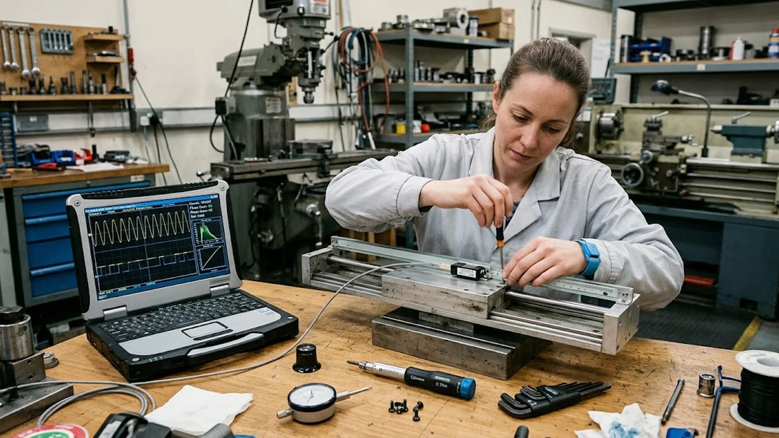
Optical Encoder Retrofit on Legacy Precision Stages: Interface Mapping, Mounting Adaptation, and Validation
A legacy stage with obsolete feedback electronics does not have to be retired. Retrofitting it with a modern optical encoder can restore resolution, velocity stability, and diagnostic visibility at a fraction of the cost of a new machine—provided the retrofit is treated as a system integration project rather than a parts swap. This guide walks through the baseline measurement, mechanical adaptation, interface mapping, and acceptance validation that separate a retrofit which performs for another decade from one that introduces new error sources.
Published
DIRECT ANSWER
What should a buyer prioritize?
An optical encoder retrofit replaces the feedback system of an existing stage—an aging or obsolete scale, an unsupported readhead, or analog electronics no longer serviceable—with a modern optical linear encoder, while keeping the mechanics, drives, and controller investment intact. Done correctly, it restores position resolution, improves velocity stability in the servo loop, and adds diagnostics the original machine never had. Done carelessly, it introduces new error sources: scale misalignment, Abbe offsets the original design never had, cable routing that couples noise into the count, and a reference routine the controller cannot execute.
A successful retrofit follows the same discipline as a new machine build, compressed into four steps: measure the stage's current positioning behavior as a baseline, adapt the mechanics (scale mounting, bracket stiffness, air gap, cable flex path) to the old structure, map the new encoder's signal interface and homing behavior onto the existing controller, and validate the finished axis against the baseline with a documented acceptance test. The retrofit is a system project, and the parts list is the smallest part of it.
ENGINEERING CONTEXT
The decision starts with the real constraint.
Every facility with machines older than ten years eventually meets the same decision. The stage still moves smoothly, the guides and drive are healthy, but the encoder is discontinued: the readhead electronics are no longer supported, the scale is damaged and cannot be re-ordered, or the analog signal has drifted beyond what the interpolation can recover. The vendor quotes a new machine; the budget says no. Retrofit is the obvious middle path, and it is where many projects quietly go wrong. A new scale bolted onto an old carriage inherits every accommodation the original machine made—brackets machined for the old sensor, cable chains sized for different flex life, controllers that expect a different signal format or a different homing sequence. The result is a stage that counts cleanly on the bench and then loses position, jitters at speed, or homes unpredictably in the machine. The teams that retrofit successfully treat it as an integration project with a specification, a baseline, and an acceptance gate; the teams that fail treat it as a component swap and discover the error budget afterwards.
Positioning repeatability, accuracy over travel, velocity stability, and homing behavior of the existing axis recorded while the old feedback still works, so the retrofit can be judged against evidence rather than memory.
02
Mechanical adaptation package
Scale mounting surface condition, bracket design with defined stiffness, air gap and alignment tolerance feasibility on the existing geometry, Abbe arm length, and a cable flex path rated for the stage's duty cycle.
03
Interface mapping to the existing controller
Signal format conversion (or controller input replacement) verified against the controller's actual capabilities: edge rate limits, termination, quadrature or absolute protocol, alarm wiring, and commutation signals where servomotors are involved.
04
Documented acceptance test
A before/after test plan with defined instruments, positions, and pass criteria covering repeatability, accuracy over travel, homing repeatability, and signal quality at maximum speed.
BUYER MATRIX
Compare evidence, not feature labels.
Give every shortlisted supplier the same process definition and request configuration-specific proof.
Retrofit vs new machine vs electronics-only repair — where each route wins
Aspect
Encoder retrofit
New precision stage
Electronics repair only
Position performance ceiling
Set by the old mechanics plus a new, usually better, feedback chain; typically the largest single improvement available
New error budget throughout; highest ceiling but highest cost
No change to resolution or accuracy; restores the status quo at best
Mechanical risk
Scale mounting and brackets must be engineered onto an old structure; Abbe offsets and cable paths are the main traps
None — designed as a system
None
Controller integration
Signal format and homing must map onto the existing controller, or the controller input is replaced alongside
New controller and drive tuned together
Original interface preserved; success depends on obsolescent parts being findable
Cost and downtime
Moderate; days to weeks per axis
Highest; months including site integration
Lowest when parts exist; unbounded when they do not
Best fit
Healthy mechanics, obsolete or damaged feedback, controller worth keeping
Fatigued mechanics, new accuracy requirements, or duty-cycle growth
Recent machines with a single failed module and available spares
Why the feedback chain is the right place to spend a rebuild budget
A precision stage ages unevenly. The mechanical loop—guides, bearings, drive screw or linear motor, structure—often retains most of its original capability for decades when it has been used gently and maintained, because nothing in it wears fast under laboratory duty. The feedback chain ages differently: readhead electronics go end-of-life, LED illuminators dim past the signal budget, scale coatings degrade, and the interpolation electronics that were serviceable in 2010 have no successor part. When the feedback is the limiting subsystem, every other improvement is wasted—stiffer brackets and better servo tuning cannot recover information the sensor never produced.
That asymmetry is what makes the encoder retrofit economically attractive. Replacing a discontinued scale and readhead with a modern optical encoder typically improves resolution by one to two orders of magnitude, brings sub-divisional signal quality the original analog chain never had, and adds alarm and diagnostic outputs the controller can finally act on. It is the cheapest path to a materially better axis—provided the retrofit team respects that the new encoder will measure the old machine's errors honestly, including errors the original, coarser feedback never revealed. Planning that honesty into the project, rather than discovering it at commissioning, is the difference between the two outcomes described in the precision motion application overview.
Baseline first: measure the axis before you open it
The first deliverable of a retrofit is a baseline record, taken while the old feedback still works: positioning repeatability over representative travel, accuracy across the full stroke with an external reference where one exists, velocity stability at the speeds the process actually runs, and homing or reference behavior including its repeatability. This record does three jobs. It confirms that the mechanics are genuinely healthy enough to justify the retrofit—it is a poor investment to attach a 1 nm-class encoder to a stage whose repeatability is limited by a worn guide. It sets the pass criteria for the acceptance test, so the project ends against numbers instead of impressions. And it identifies where the old axis lost performance, which is frequently the feedback chain itself: a signal amplitude barely above the interpolation threshold, a scale with a visible scratch, or a reference switch whose repeatability is several encoder periods wide.
The baseline also disciplines the specification for the new encoder. Travel plus overtravel determines scale length; maximum velocity and the controller's edge-rate limit determine the output frequency the interface must carry; the existing homing strategy determines whether an incremental encoder with a reference mark is sufficient or whether an absolute interface would remove a problematic homing sequence entirely. Teams that skip the baseline routinely over-specify resolution and under-specify the mechanical and interface constraints—the errors, as it happens, that a retrofit actually bites on.
Mechanical adaptation: fitting a new scale to an old structure
The mechanical package is where retrofit projects are won or lost, because the new scale's installation tolerances must be met on a structure designed for somebody else's sensor. The scale mounting surface has to be checked for flatness and cleaned or re-machined; the bracket connecting readhead to carriage must be redesigned with defined stiffness, because a bracket that was adequate for an old coarser sensor can still flex enough to modulate a modern fine-pitch signal; and the working air gap must be achievable and holdable across the full travel, over the temperature range the machine sees. Each of these is a known failure mode with a known remedy, catalogued in the guide to linear encoder installation alignment errors, and the retrofit context adds one more: the old structure's thermal behavior. A scale material with a coefficient of expansion mismatched to the legacy base will turn every degree of ambient drift into counted position error that the machine's compensation never knew about.
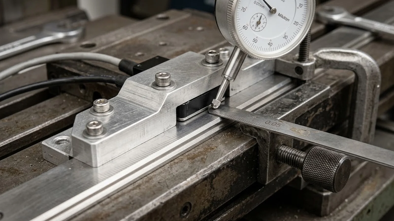
Two constraints deserve special attention on legacy machines. First, Abbe offset: the new readhead will not sit where the old sensor sat, and if the measuring line moves farther from the process point, angular errors of the old guides convert into larger positioning errors at the workpiece. The bracket design should pull the measuring line toward the original axis of measurement, not wherever it bolts conveniently. Second, the cable path: legacy cable chains and strain reliefs were sized for the old cable, and a modern encoder cable with different flex requirements must be routed with its minimum bend radius and flex life respected, or the retrofit will fail six months later with an intermittent count fault nobody associates with the mechanical work. The detail image below shows the as-built reality: brackets adapted to the old carriage, dial indicators verifying alignment, and the air gap being set before the readhead is finally torqued.
Interface mapping: making the new encoder speak to the old controller
The second half of the retrofit is electrical. The existing controller's feedback input defines what the new encoder must deliver, or what conversion hardware must deliver on its behalf: differential TTL quadrature with defined edge rates, a line-driver signal the legacy input can terminate correctly, or a serial absolute protocol the controller was never built to read. Mapping this early avoids the most expensive retrofit mistake—installing an encoder whose signal the controller cannot use in its current firmware, discovered after the mechanical work is complete. The practical options, and the signal-level details that decide among them, are laid out in the guide to TTL and line driver output interfaces.
Interface mapping also covers the reference system. A retrofit that changes the encoder's index or reference mark geometry changes the homing sequence, and a homing routine tuned for the old sensor can be genuinely unsafe with a new one—latching on a different edge, at a different speed, or with different repeatability. The controller's homing configuration must be re-derived against the new encoder's reference behavior, using the same discipline as the original design, as described in the index pulse and homing reference guide. Where the retrofit moves to an absolute interface, the machine gains power-cycle position retention but inherits a startup validation obligation; where it stays incremental, the reference switch placement and the count-latching speed become part of the acceptance test rather than an afterthought.
Acceptance: closing the retrofit against the baseline
A retrofit is finished when the axis is demonstrated to be better than the baseline, not when the readhead lights up. The acceptance test mirrors the baseline record: repeatability at the same positions, accuracy over the same travel, velocity stability at the same speeds, and homing repeatability with the new reference system, all with the instruments, temperatures, and pass criteria written down. Signal quality at maximum speed belongs in the same record—amplitude margins, quadrature symmetry, and count stability under acceleration—because a retrofit that passes static tests and fails under motion will surface later as servo tuning complaints. Where the new encoder is a higher-class device than the old one, an incoming acceptance test before installation, following the same structure as the guide to optical encoder incoming acceptance testing, keeps the supplier's specification and the machine's reality in the same file from day one.
Documentation closes the loop. The retrofit file should contain the baseline, the bracket and installation drawings as built, the achieved air gap and alignment readings, the controller configuration diff (gain changes, homing sequence, alarm wiring), and the final acceptance record. This is not bureaucracy; it is what makes the next obsolescence event—a failed readhead in eight years, a controller upgrade in twelve—solvable in days instead of weeks, because the machine's feedback architecture exists on paper and not only in the head of the engineer who did the work.
CONCLUSION
Retrofit the feedback like a system, and the old stage earns a second decade.
An optical encoder retrofit is one of the highest-leverage investments available to a facility with aging precision machinery: the guides and drives are kept, the feedback chain—the subsystem that usually triggered the decision—is renewed, and the axis returns with better resolution, cleaner signals, and diagnostics the original machine never offered. The failure modes are equally well known: skipped baselines, brackets that ignore stiffness and Abbe offset, cable paths that ignore flex life, and interface mappings that leave homing behavior undefined.
Treat the retrofit as a four-step system project—baseline, mechanical adaptation, interface mapping, acceptance against the baseline—and each of those failure modes has a gate that catches it. The parts list is the smallest deliverable. The engineering record is what turns an old stage with a new encoder into a machine the next engineer can still maintain a decade from now.
Baseline test record: repeatability, accuracy over travel, and velocity stability of the axis before the retrofit, measured on the old feedback
Mechanical package: bracket drawings, achieved air gap and alignment readings against the supplier's tolerance table, Abbe arm length as built
Interface verification: signal quality at maximum speed (amplitude, symmetry, edge rate), termination, alarm behavior, and controller configuration listing
Acceptance test: before/after repeatability, accuracy, and homing repeatability with instruments, temperatures, and pass criteria recorded
FAQ
Questions engineers ask before selection.
When is a retrofit not worth it, and a new stage is the better answer?
When the baseline shows the mechanics, not the feedback, are the limiter—worn guides, degraded drive performance, or structure drift that no sensor can compensate—a new stage is the honest answer. Retrofit is the right route when mechanics are demonstrably healthy and the feedback chain is obsolete, damaged, or unsupported.
Can I keep my existing motion controller after an encoder retrofit?
Usually, yes, if the new encoder's signal format is mapped to the controller's input capabilities—differential TTL quadrature and line-driver signals are the most common retrofit cases. Moving to a serial absolute interface may require a controller input card or protocol converter. Verify edge-rate limits, termination, and homing configuration before ordering the encoder, not after installing it.
How much better will the axis be after replacing the encoder?
The feedback chain improves by the ratio of the two systems' specifications—often one to two orders of magnitude in resolution—but the axis result is bounded by the mechanics. The baseline measurement predicts the ceiling: expect the new axis to approach the old mechanics' intrinsic repeatability, which the old coarse feedback was masking.
Should the retrofit use an incremental or absolute encoder?
Follow the machine's needs, not the catalog. If the existing homing sequence is fast, repeatable, and safe, an incremental encoder with a reference mark keeps the controller and wiring changes minimal. If homing on the legacy machine is slow, unreliable, or hazardous, the retrofit is a natural moment to move to absolute feedback—but budget for the startup validation the absolute architecture requires.
What is the single most common retrofit failure you see?
Mechanical adaptation done by eye: a bracket reused or copied from the old sensor without checking stiffness and Abbe offset, an air gap set once at room temperature, and alignment readings never taken. The encoder works on the bench and then produces position errors, count loss, or intermittent faults under real motion and thermal conditions. An hour of dial-indicator work during installation prevents most of it.