Optical Encoder Output Interfaces: Choosing Between TTL, Line Driver (RS-422), Open Collector, and Push-Pull
The electrical interface of an incremental encoder decides how far its signals travel, how much noise they survive, and which counters can read them. This guide explains TTL square wave, line driver (RS-422), open collector, and push-pull outputs, their cable-length and noise behavior, termination and EMC practice, and how to match the output to the receiving counter or controller.
Published
DIRECT ANSWER
What should a buyer prioritize?
An incremental encoder's output interface is the electrical circuit that turns the readhead's optical signals into voltages a counter or controller can read, and choosing it is mostly a decision about cable length, electrical noise, and receiver compatibility. TTL square wave outputs deliver clean 5 V single-ended logic that is easy to read over short distances but degrades quickly beyond a few meters in electrically noisy environments. Open collector outputs let the receiver set the signal level through a pull-up resistor, which makes them adaptable to 5–24 V counting inputs, but they are slow at the edges, noise-sensitive, and single-ended. Push-pull outputs drive both logic states actively, hold their level better over longer runs, and tolerate higher supply voltages.
For anything beyond a short, quiet machine, the robust choice is a line driver with differential RS-422 signaling: each channel is sent as a complementary pair over twisted pairs, so noise couples equally into both wires and is cancelled at the differential receiver, allowing tens of meters of cable and reliable operation near drives, inverters, and switching supplies. The selection sequence that works in practice is to fix the cable length and the electromagnetic environment first, confirm the receiver input circuit next, and only then choose among TTL, open collector, push-pull, and line driver—because an interface that is electrically ideal but incompatible with the counter input still fails.
ENGINEERING CONTEXT
The decision starts with the real constraint.
Output interface problems rarely show up on the bench, where a readhead is connected to a counter by half a meter of cable. They show up after installation, when the encoder cable runs alongside a servo drive for six meters and the position readout starts accumulating counts that never happened mechanically. A single-ended TTL output that looked crisp at short range arrives at the counter with edges slowed by cable capacitance, logic thresholds sitting inside a noise window, and ground potential differences between encoder and receiver adding offset. Open collector outputs add their own traps: a missing or wrongly sized pull-up leaves floating inputs that count sporadically, and slow rising edges cause doubled counts at speed. Even differential line driver systems can be installed badly—termination left off on long runs, pairs not twisted, shield grounded at both ends of unequal grounds—and produce jitter or missed steps that look like encoder faults. Because the symptom appears at the counting electronics while the cause sits in the output stage, cabling, or grounding, interface selection mistakes are usually diagnosed as encoder quality problems, and the replacement encoder behaves identically.
Measure or fix the distance between encoder and receiver, and note what the cable will run next to. Cable length and adjacent noise sources (drives, contactors, solenoids) eliminate most interface options before any datasheet detail matters.
02
Receiver input circuit documented
Identify whether the counting input is 5 V TTL logic, a 24 V digital input, a differential RS-422 receiver, or a high-impedance single-ended input. The output interface must match the receiver's threshold, voltage range, and input structure—this is a compatibility decision, not a preference.
03
Counting rate with margin
Calculate the maximum edge frequency from line count and maximum velocity, including the electrical edge rate the interface must support, then select an output stage and cable combination with margin above the required rate.
04
EMC provisions in the cabling plan
Specify twisted-pair differential cabling for line driver outputs, shield termination per the machine's grounding scheme, and termination resistors where cable length warrants them, so the chosen interface performs as designed in the installed environment.
BUYER MATRIX
Compare evidence, not feature labels.
Give every shortlisted supplier the same process definition and request configuration-specific proof.
Incremental encoder output interfaces compared
Aspect
TTL square wave
Open collector
Push-pull (HTL)
Line driver (RS-422 differential)
Signal structure
Single-ended 5 V logic driving both states actively; A, B, and Z as square waves
Single-ended, sinking only; the receiver's pull-up resistor defines the high level
Single-ended, driving both states actively at supply level, commonly 5–24 V
Each channel sent as a complementary pair (A and A-inverted) over a twisted pair; differential receiver recovers the signal
Noise immunity
Modest: single-ended edges and a shared ground reference make it vulnerable to coupled noise
Lowest: floating lines when unpulled, slow edges, and a large threshold window invite noise counts
Better than TTL on level margin due to higher voltage swing, still single-ended
Highest: common-mode noise coupled into both wires of a pair is rejected by the differential receiver
Practical cable length
Short runs, typically up to a few meters in a clean electrical environment
Short runs; length limited further by pull-up sizing and edge slowdown from cable capacitance
Moderate runs, with level margin helping at 24 V
Long runs, commonly tens of meters, with termination at the receiver for length and speed
Receiver compatibility
5 V logic counters and controller inputs expecting TTL levels
Wide: pull-up to 5–24 V lets one output serve different counting inputs; check input must not source reverse current
24 V PLC and counter inputs, and 5 V inputs where the datasheet permits
Controllers with differential RS-422 line receiver inputs; converters exist for receivers without them
Best use
Short internal connections in instruments and clean enclosures
Legacy counters, mixed-voltage inputs, and simple short links where cost dominates
Industrial 24 V environments with moderate cable runs
Precision machines, long cables, electrically noisy environments, and any application where count integrity matters
What the output stage actually determines
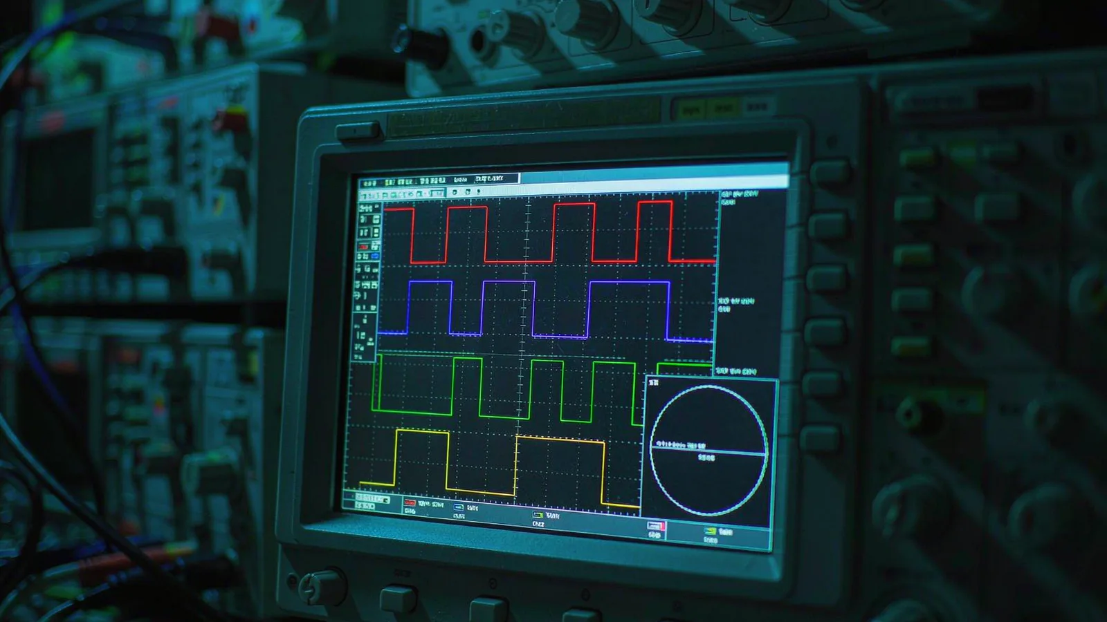
Inside an optical encoder, the photodetector signals are conditioned into clean incremental channels: two square waves in quadrature (A and B) whose phase relationship defines direction, plus a reference mark (Z). The output interface is the final stage of that conditioning, and it determines three things a system designer cares about. First, signal levels and structure: whether the receiver sees 5 V logic, a 24 V industrial level, a pulled-up current sink, or a differential pair. Second, drive strength and edge quality: how much cable capacitance the output can charge, and how fast the edges remain at the end of the cable, which sets the usable counting frequency together with the receiver's bandwidth. Third, noise behavior: how much of the electrical environment on the factory floor or inside the instrument couples into the position signal.
These three properties interact with the receiving counter, which is why interface selection is a system decision rather than an encoder feature. A counter input designed for 24 V signals will not read a 5 V TTL output reliably; a high-speed TTL counter may be damaged by 24 V push-pull levels; a differential receiver expects a complementary pair that single-ended outputs do not provide. Matching output to input comes first, and only then do distance and environment refine the choice. Where the receiver is a servo drive or motion controller, its encoder feedback specification usually states the acceptable interface types explicitly.
Line driver outputs and differential RS-422 signaling
A line driver output contains a transmitter that drives each channel as two complementary signals—A and its inverse, B and its inverse, Z and its inverse—over a twisted pair each. The receiver end uses a differential line receiver that responds only to the voltage difference between the two wires. Electrical noise picked up along the cable—magnetic fields from motor cables, switching transients from inverters, ground potential differences between encoder and controller—couples into both wires of a pair almost equally, and the receiver's common-mode rejection removes it. This is why differential line driver interfaces tolerate cable runs of tens of meters and operate reliably in cabinets shared with drives and switching supplies, while single-ended signals over the same path accumulate errors.
The practical requirements are straightforward but must be enforced. Cable should use twisted pairs with the complementary signals paired together, overall shielded, with the shield terminated according to a defined grounding scheme rather than improvised. For longer runs and higher counting rates, terminating resistors matched to the cable characteristic impedance are placed at the receiver to absorb reflections; for short runs they are usually unnecessary. Supply the line driver from a clean 5 V rail and check that the encoder datasheet's maximum output frequency still holds at the end of the specified cable, since edge rates slow with cable capacitance. On the bench and during commissioning, the differential pair structure is also a diagnostic gift: viewing the A/A-inverted pair on an oscilloscope shows immediately whether noise is common-mode (acceptable) or differential (a wiring or grounding problem).
An open collector output switches only to the low state; the high state exists because a pull-up resistor at the receiver end lifts the line to the chosen voltage. This structure is flexible—one output can serve a 5 V counter or a 24 V PLC input simply by choosing the pull-up voltage, provided the output transistor and the receiver input tolerate it—and it is the traditional interface on cost-sensitive and legacy industrial encoders. Its weaknesses follow from the same structure: the rising edge is shaped by the pull-up resistor charging the cable capacitance, so edges are slow, maximum counting frequency is limited, and the line sits in a floating, high-impedance state whenever the transistor is off, which is precisely when coupled noise converts into false counts. Pull-up sizing is therefore a compromise—strong enough for edge speed and noise margin, weak enough that the output can pull the line fully low—and the receiver input must never drive the line.
Push-pull (often called HTL when built at industrial supply levels) outputs switch both states actively, giving a defined low as well as a defined high without any pull-up. The signal holds its level against cable capacitance far better than an open collector, and at 10–30 V supply the large voltage swing provides generous threshold margin for 24 V industrial inputs over moderate cable lengths. Push-pull remains single-ended, however, so it shares the fundamental susceptibility of all single-ended signals to ground offsets and coupled noise; it improves level margin, not common-mode rejection. For both open collector and push-pull interfaces, keeping the encoder ground reference and the receiver ground tied at one defined point, and routing signal cable away from power cable, does more for signal quality than any datasheet parameter.
Termination, signal integrity, and matching the counter
Whatever the interface, commissioning should include an electrical check at the receiver end rather than at the encoder. The questions are concrete: do edges meet the receiver's rise-time expectations at maximum speed, is the duty cycle still close to 50 percent, is quadrature phase within the window the counter needs for direction decoding, and does the Z pulse arrive within its specified width? Reflections on unterminated long lines appear as steps and overshoot on edges; excessive cable capacitance appears as rounded edges that shave counting margin at speed; a marginal pull-up on an open collector input appears as an erratic high level. Each has a distinct scope signature and a distinct fix—termination, shorter or better cable, or corrected pull-up.
The final compatibility check is functional: run the axis through a defined motion sequence and compare counted position against a mechanical or optical reference, in both directions and including reference-mark homing. Count integrity is the actual requirement, and it is verified at the machine, not inferred from the datasheet. When an existing encoder must feed two receivers, or an interface conversion is needed between a line driver encoder and a single-ended counter, the structured approach is the same as for any signal distribution decision; the signal splitting and dual-output guide covers the divider, buffer, and isolation options in detail. For high line counts and fast stages, the counting frequency limits of both the output stage and the receiver become the binding constraint and deserve their own calculation.
Match the interface to the cable and the counter, in that order.
Output interface selection is not about which circuit is best in the abstract; it is about which circuit survives the cable length, the electrical environment, and the receiver that will actually read it. TTL square wave serves short, quiet links; open collector serves legacy and mixed-voltage inputs at short range with disciplined pull-up practice; push-pull serves 24 V industrial inputs with better level margin; and differential RS-422 line driver signaling is the default for precision machinery, long cables, and noisy environments because common-mode rejection is the one property none of the single-ended options can replicate.
The working procedure is short: fix cable length and environment, document the receiver input, calculate the required counting rate with margin, choose the interface that satisfies all three, and verify at the receiver end—edge shape, quadrature phase, and counted position against reference—before releasing the machine. Machines commissioned this way do not accumulate phantom counts, and encoder signals stop being a suspect when other faults appear.
Encoder datasheet naming the output circuit (TTL, open collector, push-pull, or line driver per RS-422), supply voltage, and maximum output frequency
Receiver input specification showing logic family, threshold levels, input impedance, and whether differential inputs are available
Cable specification: twisted pairs for differential signals, capacitance per meter, shield type, and flex rating for moving applications
Signal check at the receiver end during commissioning: measured edge shape, duty cycle, and quadrature phase at maximum operating speed
Count integrity verification over a defined motion sequence, comparing counted position against a mechanical reference after installation
FAQ
Questions engineers ask before selection.
What is the difference between TTL and line driver encoder outputs?
A TTL output is a single-ended 5 V square wave referenced to ground, suited to short cable runs in clean environments. A line driver output sends each channel as a complementary pair over a twisted pair using differential RS-422 signaling, which the receiver reads as the difference between the two wires. The differential structure rejects common-mode noise and supports cable lengths of tens of meters, while single-ended TTL degrades much sooner.
How long can an encoder cable be?
It depends on the interface and the electrical environment. Single-ended TTL and open collector outputs are typically limited to a few meters; push-pull at 24 V tolerates moderate runs; differential RS-422 line driver outputs commonly reach tens of meters with proper twisted-pair cabling and, at higher speeds or lengths, termination at the receiver. The encoder datasheet's maximum cable length and output frequency figures should be treated as the limit unless a signal check at the receiver end proves otherwise.
Does an open collector encoder output always need a pull-up resistor?
Yes. An open collector output only pulls the signal low; without a pull-up resistor at the receiver the line floats when the transistor is off, producing undefined logic levels and sporadic false counts. The pull-up voltage is chosen to match the receiver input (commonly 5–24 V), and the resistor value balances edge speed and noise margin against the output transistor's sink capability.
Can a differential RS-422 encoder be connected to a single-ended counter input?
Not directly, but conversion is routine. Using only one wire of each complementary pair with a common ground is a poor solution because it discards the noise immunity the differential interface was chosen for. The correct options are a differential-to-single-ended converter (a line receiver circuit) or a purpose-built signal splitter, placed close to the encoder end of the long cable run so differential signaling still protects the majority of the path.
When is termination needed on encoder signal lines?
Termination at the receiver is warranted when the cable is long relative to the signal edge rate—roughly when the round-trip electrical delay becomes a significant fraction of the edge time—which on typical encoder data rates means runs of ten meters and beyond, especially with fast line driver edges. For short runs, termination is usually omitted because it needlessly loads the driver. The criterion is the measured signal: clean edges without steps or overshoot need no change.