
Signal-type fidelity
Match the splitter to the exact signal: analog quadrature amplitude and edge quality preserved for interpolation electronics, or protocol-conformant timing for BiSS-C, EnDat and similar frames.
TECHNOLOGY / ENCODER SIGNAL DISTRIBUTION
When one encoder must feed two controllers, a motion recorder and a safety monitor, or a redundant feedback pair, the signal splitter decides whether both consumers see a clean signal. This guide covers splitter types, buffer and amplifier considerations, cable architecture and the installation and commissioning checks that keep both outputs honest.
Published
DIRECT ANSWER
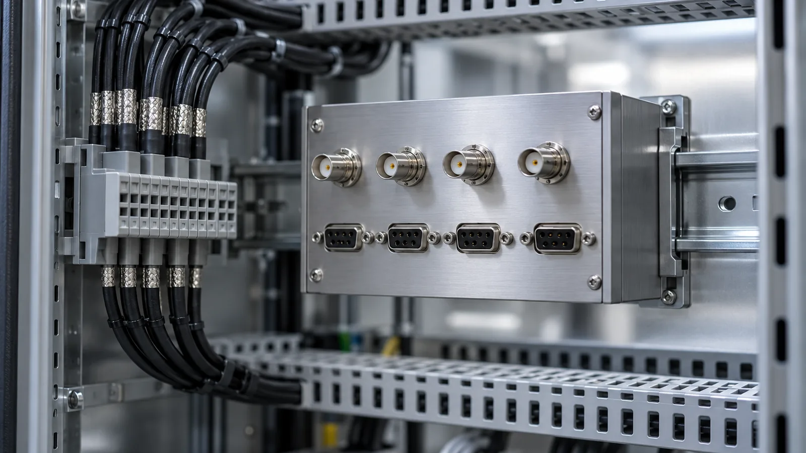
An encoder signal splitter takes the output of one encoder and drives two or more consumers from buffered copies of the same signal. It is used for redundant controller feedback, for feeding a motion controller and a diagnostic or data-acquisition device in parallel, and for distributing position data where a second encoder is mechanically impossible. The splitter must actively buffer and amplify the signal; a passive Y-branch that merely wires two inputs to one output loads the source, degrades edge rates and invites noise, and should not be used with precision encoder signals.
Specify the splitter for the exact signal type, quadrature levels or serial protocol, the number and length of output branches, and the isolation or galvanic separation the redundancy concept requires. Then commission it as part of the feedback system: verify both outputs against the source, confirm timing skew is acceptable for the faster consumer, and document the comparison test so signal drift on either branch is detected during service rather than during a failure investigation.
ENGINEERING CONTEXT
Signal distribution is usually designed last, after the encoder, the controllers and the cabinet layout are fixed, and by then the only question asked is whether a splitter box exists that fits the connector. The difficult questions live underneath that. Does the redundancy concept actually require galvanic isolation, or will a shared ground turn one consumer's fault into both consumers' problem? Does the buffer preserve the analog quality of a 1 Vpp sinusoidal signal that an interpolation electronics depends on, or does it merely reproduce logic edges? Does the serial protocol survive a repeater's added propagation delay at the configured clock rate? And when one output branch shows an intermittent fault, is it the encoder, the splitter or the branch that fails, and who can tell the difference without a documented baseline? Installations that skipped these questions work at handover and drift into intermittent position faults that consume days of service time. The fix is to treat the splitter as a component of the feedback chain with its own specification, its own commissioning record and its own comparison test.
Discuss your requirement ↗CRITICAL REQUIREMENTS
Match the splitter to the exact signal: analog quadrature amplitude and edge quality preserved for interpolation electronics, or protocol-conformant timing for BiSS-C, EnDat and similar frames.
Define whether output branches need galvanic isolation from each other and from the input, and how shields and grounds are routed so a fault on one consumer cannot propagate to the other.
Account for every output branch: count, cable length, receiver input impedance and the resulting load on the buffer, with margin against the splitter's drive specification.
Provide a documented way to compare outputs against each other or against the source, so a degraded branch is identified as a branch problem and not as an encoder fault.
BUYER MATRIX
Give every shortlisted supplier the same process definition and request configuration-specific proof.
| Selection factor | Passive Y-branch wiring | Active splitter with buffering | Second physical encoder |
|---|---|---|---|
| Signal integrity | Degrades with every added input; loading reduces amplitude and edge rate | Buffered and amplified per branch; source sees one defined load | Independent sources; no shared signal path |
| Isolation capability | None; all consumers share grounds | Isolation available per design; grounds separable | Full electrical independence |
| Serial protocol support | Not usable for BiSS-C, EnDat or similar point-to-point frames | Repeater or fan-out units with protocol-conformant timing | Each encoder addressed independently |
| Redundancy value | None; a source fault disables all consumers | Distribution redundancy only; the encoder remains a single point | True sensor redundancy for safety or availability concepts |
| Cost and complexity | Lowest, and often the most expensive in service time | Moderate; one specified module plus commissioning | Highest; mechanical integration and a second alignment |
| Typical fit | Not recommended for precision feedback | Controller plus diagnostics, redundant controller inputs, long distribution runs | Safety-rated axes and machines requiring sensor-level redundancy |
The situations recur across machine types. A motion controller and a data-acquisition or calibration system both need the same position signal, and adding a second encoder changes the mechanics, the alignment and the budget for a signal nobody reads continuously. Two drives on a gantry each want feedback from the same axis for cross-checking. A safety or monitoring layer must observe position independently of the servo controller without having its own readhead. Retrofit work often adds a monitoring system to an axis whose encoder has no spare outputs. In all of these, distribution from one source is the practical answer, and the splitter is the component that makes it work.
What the splitter must protect is the property that made the encoder selected in the first place: signal quality at the receiving end. Each additional consumer adds input capacitance, bias current and a cable run, and every one of them attenuates amplitude, slows edges and admits noise if the sharing is done passively. The engineering question is therefore not whether signals can be wired in parallel but how each branch receives a signal as clean as it would have received alone.
For analog quadrature, the splitter's buffer must preserve amplitude, phase relationship and edge linearity, because downstream interpolation electronics judge position from the ratio of sine and cosine signals. A buffer that clips, offsets or phase-shifts the signal introduces subdivision error on every output branch, identically and invisibly. The specification to require is fidelity at the working frequency: amplitude and phase behaviour across the signal bandwidth the axis actually produces at maximum velocity, not a bandwidth figure quoted for logic levels.
For digital square-wave quadrature the concern shifts to edge rates and timing skew between branches, which set the cable-length budget of the fastest consumer. For serial absolute protocols, point-to-point frames such as BiSS-C or EnDat are not simply fanned out with wire; repeater or fan-out units must reproduce clock and data with propagation delay and skew inside the protocol's timing budget at the configured clock rate. Each protocol repeater is a specific design for a specific protocol and clock range, and the implementation sheet of the exact unit, matched against the encoder and both masters, is the evidence that the timing works rather than a hope that it does.
Redundant feedback is meant to survive the failure of one path, and the isolation design decides whether it does. If both controller inputs share a ground through an unisolated splitter, a ground fault, a damaged cable or a shorted receiver on one branch can drag the other branch down with it, converting a redundant concept into a common-mode failure. Galvanic isolation between branches, and between input and outputs where the concept requires it, keeps each consumer's electrical environment its own, and the isolation voltage rating should be stated for the installation's conditions rather than assumed.
Grounding follows the same logic. The splitter is where shields and reference potentials from two cabinets meet, so the shield routing plan belongs to the splitter drawing, not to improvisation at installation. Route input and branch cables as shielded lines per the encoder EMC guidance, terminate shields per the grounding concept, and keep the splitter's supply separate from noisy loads. A splitter that solves the signal-sharing problem but bridges two grounding domains has traded an installation convenience for a latent fault.
Plan the distribution like any signal path, with a budget per branch. Start from the splitter's drive specification: how many branches it supports, the maximum cable length per branch at the working frequency or clock rate, and the receiver loading it assumes. Then account for the real installation, branch by branch, including connectors, junctions and any longer run to the second consumer that was the reason for the splitter. A branch that exceeds the budget does not fail at handover; it fails at temperature extremes, after vibration loosens a connector, or whenever noise coincides with an edge, which is the worst kind of intermittent to diagnose.
Physical placement matters as much as the budget. Mount the splitter close to the encoder where the raw signal is strongest, treat the input run as the critical short one, and let the buffered, amplified signals carry the longer distances. Give the module the same environmental protection assumed for the drive cabinet, and label every branch permanently: an unlabelled splitter in a cabinet is a fault-diagnosis tax paid for years.
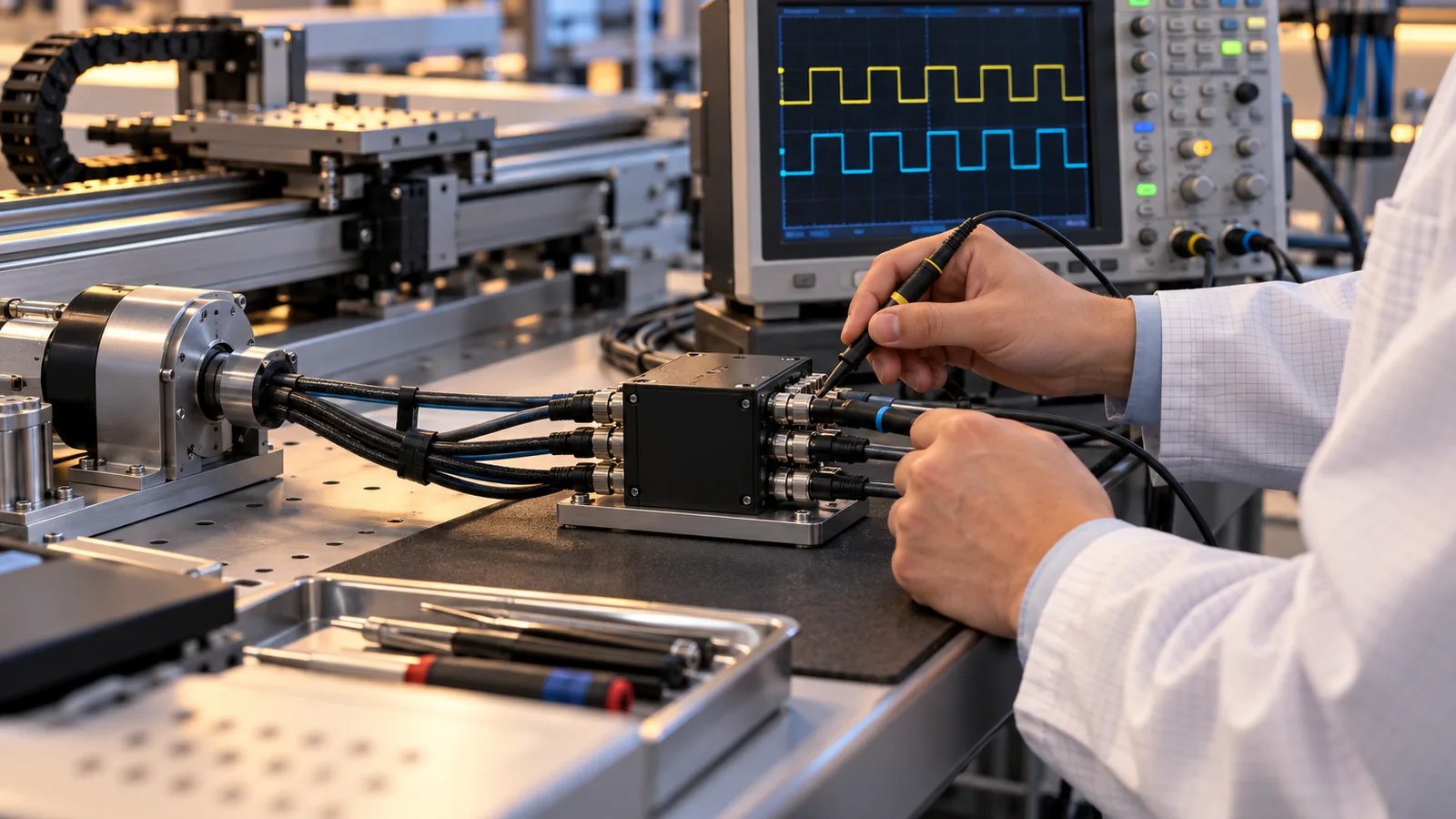
Commission the splitter as part of the feedback system, not as a cable fitting. The core test is a comparison: with the axis moving through a representative motion profile, capture the input signal and each output branch and verify amplitude, phase or timing relationship and protocol behaviour against the splitter's specification. For serial protocols, confirm both masters read identical positions across travel and that error counters or warnings stay clean. Where consumers differ in speed or sensitivity, test the most demanding one, because a branch that satisfies a slow diagnostic input may still be marginal for a fast servo loop.
Then make the comparison repeatable. Record the reference captures, the acceptance criteria and the instrument settings as part of the machine documentation, so that a future intermittent fault on one consumer can be checked against a baseline instead of argued about. A documented branch comparison turns the classic three-way dispute, encoder, splitter or controller, into a five-minute measurement, and that is the practical return on treating the splitter as a specified feedback component.
CONCLUSION
A signal splitter is a small component with a large share of the feedback chain's reliability, because everything both consumers receive passes through it. Match it to the exact signal type and protocol, design the isolation and grounding so redundancy survives a single fault, budget every output branch like a signal path, and commission it with a documented comparison between source and branches. Installed this way, one encoder can serve two masters for years without either of them noticing the other.
EVIDENCE CHECKLIST
FAQ
Passive parallel wiring loads the encoder source, reduces signal amplitude and edge rate, and shares grounds between consumers, so it is not suitable for precision feedback. An active splitter with buffered outputs gives each consumer a clean, separately driven signal.
Point-to-point frames such as BiSS-C and EnDat are not passively fanned out. Protocol-specific repeater or fan-out units reproduce clock and data within the timing budget, and the exact unit must be validated for the encoder, both masters and the configured clock rate.
When the redundancy concept must survive failure of the encoder itself, a splitter cannot provide that because the source remains a single point of failure. Safety-rated axes and high-availability machines justify the mechanical integration and alignment cost of a second physical encoder.
Close to the encoder, so the raw input signal travels the shortest distance and the buffered outputs carry the longer runs to the consumers. Provide the same environmental protection as the control cabinet and label every branch for service.
Compare the suspect branch against the input signal and the other branch using the documented baseline from commissioning. If the input and other branches are clean, the fault is in the branch cable or receiver; if all outputs share the distortion, look at the input path or the encoder.
AUTHORITATIVE SOURCES
TECHNICAL REVIEW
Send the application, critical parameters and any drawing or process information available.
Discuss your application ↗