
A measured site spectrum
Floor vibration measured with a calibrated instrument over a full day and night, reported as velocity or acceleration against frequency for the actual installation position and mounting configuration.
TECHNOLOGY / STAGE METROLOGY
A stage specified to nanometres will not hold that accuracy if the floor moves. This guide explains floor vibration criteria, how to measure the site, where isolation belongs in the design and how to specify a platform that meets the process instead of the catalogue.
Published
DIRECT ANSWER
Floor vibration criteria describe how much the ground under a precision tool is allowed to move at each frequency, and they are the starting point for any stage that claims nanometre performance. Walking traffic, building services, lifts and nearby roads inject vibration across a wide band, and a precision stage cannot distinguish motion of the floor from motion of the tool it is supposed to position. If the floor moves more than the specification, the stage is measuring and fighting the building, and no amount of servo tuning will recover the lost accuracy.
The practical sequence is measure first, then specify. Measure the site with a calibrated accelerometer or seismometer over a full day and night to capture the worst case, express the result as a velocity or acceleration spectrum, and compare it against a vibration criterion chosen for the actual feature size and process. Only then decide whether a stiffer slab, a lower-vibration location, a passive isolation platform or an active isolation system is required, and specify the isolation to complement the stage rather than in isolation from it.
ENGINEERING CONTEXT
A new precision tool passes its factory acceptance test in the workshop and then fails to hold tolerance on site. The stage, the encoder and the servo loop are unchanged, yet the measurement scatter is several times larger and the results depend on the time of day. The workshop floor was a solid slab in a quiet building; the installation site is an upper floor with an air-handling unit nearby and a corridor outside the door. The stage is doing exactly what it was told: it is following a floor that moves. The gap between the two results is environmental, and it can only be closed by measuring the site and adding isolation and, where possible, relocating the tool.
Discuss your requirement ↗CRITICAL REQUIREMENTS
Floor vibration measured with a calibrated instrument over a full day and night, reported as velocity or acceleration against frequency for the actual installation position and mounting configuration.
A vibration criterion selected from the smallest feature or the tightest overlay the tool must hold, not copied from a generic laboratory class.
Passive or active isolation chosen to attenuate the frequencies that actually carry energy at the site, with the stage and its mass included in the calculation.
Vibration and positioning measured on the installed tool, so the delivered performance is demonstrated on the real floor rather than inferred from a model.
BUYER MATRIX
Give every shortlisted supplier the same process definition and request configuration-specific proof.
| Option | How it works | Best for | Limit or cost |
|---|---|---|---|
| Stiff, massive foundation | A large slab or isolated block reduces low-frequency motion and spreads load | Ground-floor installations and heavy tools | Cannot help on upper floors and cannot be retrofitted easily |
| Passive pneumatic isolation | Air springs and dampers attenuate above their natural frequency | Most laboratory and production tools with mid- to high-frequency disturbance | Amplifies near its natural frequency and needs level control |
| Active isolation | Sensors and actuators cancel motion across a wider, lower band | Tools that must hold tolerance on a moving or upper floor | Higher cost and complexity; requires power and service |
| In-tool damping and stiffness | Mass, damping and structural design inside the machine reduce internal response | Any tool, alongside external isolation | Improves the machine but cannot correct a floor that moves too much |
| Relocation or scheduling | Move the tool, or run critical metrology when the building is quiet | Cases where the disturbance is avoidable or periodic | Constrains layout and workflow; not a permanent cure |
Vibration criteria are a way of stating, at each frequency, how much floor motion is acceptable for a given class of work. They are usually expressed as a velocity or acceleration limit, and they are graded: a general office, a normal laboratory and a nanometre-scale imaging or patterning tool occupy different grades. The reason the criteria are frequency-dependent is that a tool responds differently to slow sway than to fast buzz. A rigid stage on a good frame may tolerate low-frequency motion and be disturbed mainly by higher frequencies from pumps, fans and foot traffic.
The mistake to avoid is selecting a criterion by reputation. A tool that holds an overlay budget of a few tens of nanometres on a glass substrate has different needs from a scanning probe microscope, and two tools in the same room may need different criteria because their internal stiffness and their sensitivity bands differ. Derive the criterion from the process requirement, then check it against the measured site spectrum.
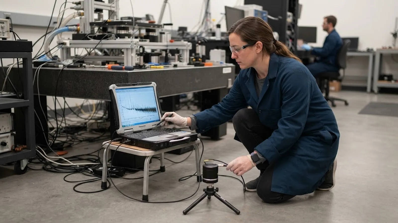
Site measurement is not complicated, but it must be done honestly. A calibrated accelerometer or seismometer is placed at the exact position where the tool will stand, at the mounting height and on the same floor structure, and data are logged over a full day and night so that the quiet and the busy periods are both captured. Foot traffic during working hours, a lift, a compressor cycling and an air handler starting can each dominate a particular frequency band, and a short daytime measurement can miss the worst case altogether.
The result is a spectrum, and spectra must be read with the tool's own response in mind. A disturbance at a frequency where the stage structure is stiff matters far less than the same amplitude near a resonance of the stage, the platform or the frame. Where the machine's modal behavior is known, the site spectrum can be weighted by it, so the isolation decision targets the frequencies that actually reach the tool point rather than the loudest number on the chart.
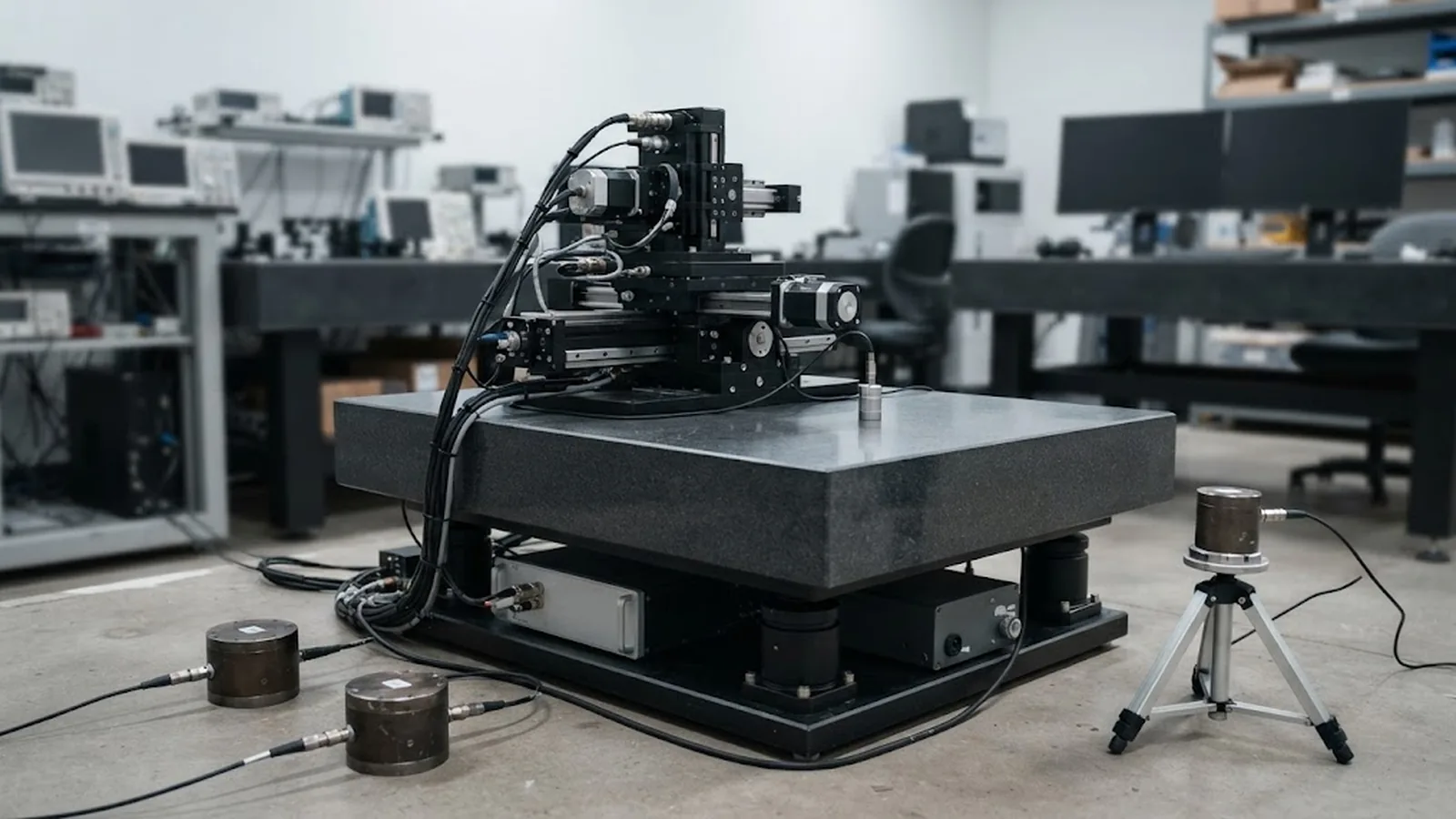
Passive isolation, typically pneumatic air springs with damping, is simple, robust and effective above its natural frequency, but it amplifies motion near that frequency. If the site has a strong low-frequency component near the isolator's natural frequency, a passive platform can make things worse. Active isolation uses sensors and actuators to cancel motion across a wider band, including lower frequencies, at the cost of power, complexity and a service requirement. Neither is universally better; the choice follows the measured spectrum and the band where the tool is sensitive.
Not every measured error is floor vibration, and treating a servo problem as a vibration problem wastes money. Internal sources such as a vacuum pump, a chiller, a cable dress that pulls on the carriage, or a linear motor that is not tuned will produce scatter that no floor isolation can remove. The clean way to separate them is to measure at the same time as the positioning error: if the stage's error correlates with the floor spectrum at the same frequencies, the disturbance is external; if it does not, the source is inside the machine or in the control loop.
Structural design inside the tool matters as much as the platform beneath it. A stiff bridge, well-damped structural paths and short, rigid load paths from the stage to the frame raise the machine's own resonances and reduce its response to whatever floors through. A well-damped tool on an active platform will always beat a compliant tool on the same platform.
A useful specification states the site spectrum, the chosen criterion, the isolation type and its attenuation band, the total moving mass and the acceptance test. It should also state the conditions at which performance is claimed: production speed, with services running, at the intended temperature, and at the intended location on the floor.
Verification belongs on the installed and running tool. Measure vibration at the tool point and positioning error at the same time, with the tool performing its real task, and compare the result with the criterion and with the factory acceptance data. Where margin is thin, the record shows which frequency band to attack, whether through a change of isolation, a change of location, or a change in when the critical work is performed.
CONCLUSION
Floor vibration is the environmental limit that quietly determines whether a precision stage can deliver its specified accuracy. Criteria are frequency-dependent, they must be derived from the process, and they are only meaningful when compared against a spectrum measured at the real installation position over a full day and night.
Measure the site first, choose a criterion that matches the smallest feature or the tightest overlay, match passive or active isolation to the frequency band that actually reaches the tool, and verify on the installed machine at production conditions. A tool specified this way holds its tolerance on the floor it actually stands on, not just on the floor where it was tested.
EVIDENCE CHECKLIST
FAQ
They state, at each frequency, how much floor motion is acceptable for a class of work. A precision tool responds differently to slow sway and to fast vibration, and internal resonances make it more sensitive in some bands than others, so a single amplitude number is not enough. A spectrum compared against the tool's own response is what determines whether the floor is suitable.
Long enough to capture the worst case, which almost always means a full day and night. Foot traffic, lifts, compressors and air handlers switch on and off through the day, and a short measurement during a quiet period can miss the disturbance that will limit the tool. The survey should also note which sources are active at each time.
It depends on the measured site spectrum. Passive pneumatic isolation is effective above its natural frequency but amplifies near it, so a strong low-frequency component can make it counterproductive. Active isolation cancels motion across a wider and lower band at higher cost and complexity. The choice should follow the frequencies that actually reach the tool.
Measure at the installed and running tool, at the intended location, with production services active and the machine performing its real task. Record vibration at the tool point and positioning error together, compare them against the chosen criterion and the factory acceptance data, and keep the result as a baseline for future changes.
AUTHORITATIVE SOURCES
TECHNICAL REVIEW
Send the application, critical parameters and any drawing or process information available.
Discuss your application ↗