
Full geometric error inventory
Define which of the six geometric components matter for the process, expressed at the tool point through the machine's actual Abbe offsets.
TECHNOLOGY / STAGE METROLOGY
Positioning accuracy is only one of the errors a linear stage makes. Straightness, pitch, yaw and roll shape the true motion of the carriage and dominate many process results. This guide explains each geometric error, the instruments that measure it and how the results feed error maps and compensation.
Published
DIRECT ANSWER
A linear stage moves in six degrees of freedom even when only one is commanded. Alongside positioning error along the axis, the carriage drifts sideways and vertically, and rotates about all three axes: yaw, pitch and roll. These geometric errors are systematic, repeatable and therefore mappable. They matter because they couple into the tool point through the Abbe offset: an angular error of a few arcseconds with an offset of one hundred millimetres displaces the tool by micrometres.
Measure them with the right instrument for each: a straightedge plus indicator or laser interferometer straightness optics for lateral drift, an autocollimator or interferometer angular optics for yaw and pitch, and electronic levels or dedicated roll fixtures for roll. Record the errors as functions of axis position, combine them with the Abbe offsets of the specific machine into an error map, and apply software compensation or mechanical correction where the process demands it.
ENGINEERING CONTEXT
Stage specifications centre on positioning accuracy and repeatability, so buyers verify exactly those numbers and assume the axis is therefore good. Then a machining or metrology process underperforms in ways that positioning tests never showed: an edge comes out non-parallel, a scan line drifts across the sample, a measured profile carries a slow bow that no amount of averaging removes. The missing explanation is usually geometric. The carriage yaws a few arcseconds over the travel, the straightness wanders a few micrometres, and the Abbe offsets of the real machine convert those angles into tool-point errors several times larger than the encoder's contribution.
Discuss your requirement ↗CRITICAL REQUIREMENTS
Define which of the six geometric components matter for the process, expressed at the tool point through the machine's actual Abbe offsets.
Assign straightness optics or straightedge methods to lateral drift, angular optics or autocollimator to pitch and yaw, and a level or roll fixture to roll.
Record every error as a function of axis position at the operating temperature, with the measurement direction and datum stated.
Specify how the map enters the machine: software compensation tables, mechanical adjustment or process-level allowances, with a re-verification interval.
BUYER MATRIX
Give every shortlisted supplier the same process definition and request configuration-specific proof.
| Error component | Physical meaning | Primary instruments | Typical process impact |
|---|---|---|---|
| Positioning error | Deviation along the commanded axis | Laser interferometer, step gauge | Feature location and scale error along the axis |
| Straightness (horizontal, vertical) | Lateral and vertical drift of the carriage path | Straightedge with indicator, laser straightness optics | Profile bows, edge parallelism, scan drift |
| Yaw | Rotation about the vertical axis as the carriage moves | Autocollimator, laser angular optics | Large Abbe coupling in the horizontal plane |
| Pitch | Rotation about the horizontal transverse axis | Autocollimator, laser angular optics, electronic level | Abbe coupling vertically; focus and height variation |
| Roll | Rotation about the commanded axis itself | Electronic level, dual-beam or dedicated roll fixtures | Tilt of mounted samples; levelling of fluid or optical processes |
| Squareness (per axis pair) | Deviation of the axis from its nominal orientation | Straightness data of both axes plus a square or optical square | Rectangularity of written, machined or measured patterns |
Every linear stage is a compromise between the motion it is asked to make and the guidance it receives. The carriage rides on bearings that are flat and straight only to a tolerance, so as it travels it drifts sideways and vertically, and it rotates slightly about all three axes. These six geometric errors exist simultaneously and systematically: each is a function of position that repeats well, which is exactly why they can be measured, mapped and largely removed.
Their importance comes from coupling. The encoder measures along its own axis, but the process happens at a tool or sample point that is offset from that axis in space. An angular error rotates the whole carriage, and the offset converts the rotation into displacement at the tool point. This is the Abbe principle in daily practice: a stage with excellent linear positioning can still deliver poor tool-point accuracy when the offsets are long. Before improving anything, compute which error times which offset actually limits the machine.
Straightness describes how the carriage path deviates from an ideal line in the horizontal and vertical planes. The classical method uses a straightedge or reference rail with a dial or electronic indicator. It is simple and effective over short travel, but the reference itself becomes the accuracy limit.
Laser straightness optics extend the method to longer travel: the beam defines the reference line and a position-sensitive detector in a carriage-mounted optics set records lateral drift as the axis moves, with wavelength-stabilised systems removing most environmental sensitivity. Whichever method is used, the practical discipline is the same: state the reference direction, measure both planes at the operating temperature, and record the curve, because a straightness number without a shape cannot drive compensation.
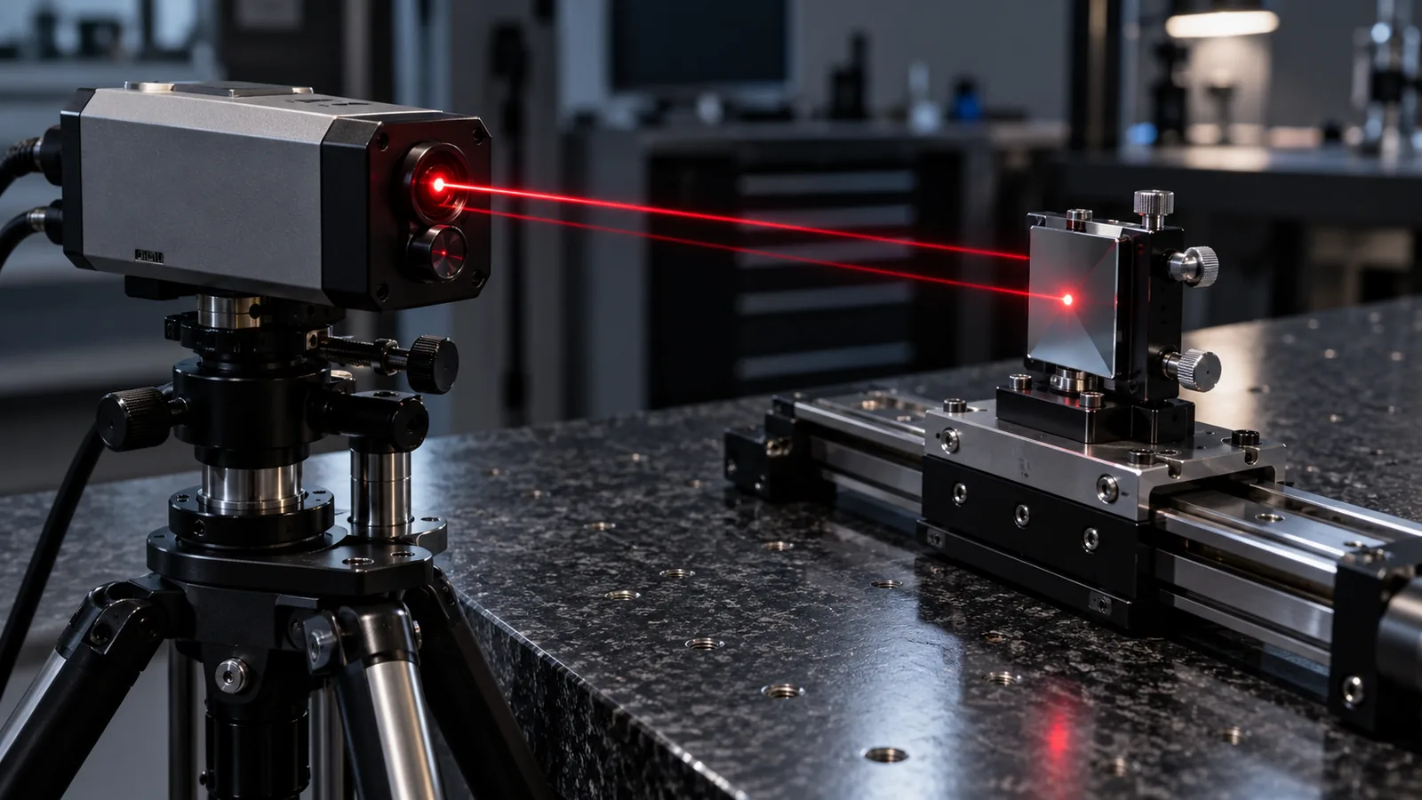
Angular errors dominate most precision machines because they multiply through Abbe offsets. An autocollimator projects a reticle image onto a plane mirror mounted on the carriage and measures the returned image shift with arcsecond-class sensitivity; stepping the mirror along the axis maps yaw and pitch as functions of position. Laser interferometer angular optics do the same job with a dual-beam arrangement, returning an angular reading directly and integrating naturally into an interferometer-based verification session already measuring positioning.
Roll, rotation about the commanded axis, is the least accessible component because no mirror geometry returns it to an autocollimator. Electronic levels measure roll against gravity; dual-beam fixtures extend the capability where gravity is not the datum. For most stages a level-based roll curve plus an honest assessment of its Abbe coupling is sufficient. In all angular measurement, the mounting of the reference mirror or optics deserves as much care as the instrument itself: a bracket that relaxes between runs will fabricate a beautiful, entirely fictional error curve.
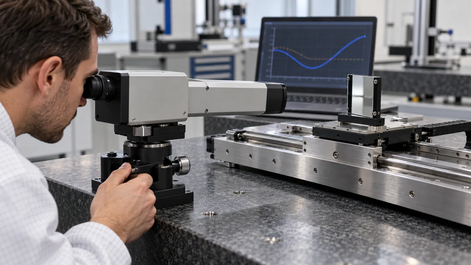
Individual error curves become useful when combined at the tool point. For each position along the travel, each straightness displacement and each angle times its Abbe offset contributes a displacement vector; summing them yields the tool-point error in the directions the process cares about. This is where priorities become arithmetic instead of opinion: a two-arcsecond yaw with a one-hundred-millimetre offset contributes about one micrometre, while a ten-arcsecond pitch on a two-centimetre stack contributes two hundred nanometres. The map tells you which correction buys real accuracy.
The map also reveals structure worth exploiting. Geometric errors are mostly smooth functions of position, so low-order terms respond well to mechanical correction, realignment of the guide or bearing adjustment, while higher-order residuals belong in software compensation tables that the controller applies as a function of commanded position. Squareness between axes is handled the same way: measured from the straightness curves of both axes or with an optical square, then compensated as a constant angular offset.
A compensation table is a snapshot of a machine that is still moving. Foundations settle, bearings wear, cable chains load the carriage differently as they route, and seasonal temperature shifts change the shape of every error curve. The map therefore needs a re-verification interval tied to the process tolerance, and every re-measurement should compare against the previous map.
Spot-check the compensated result at a few positions with an independent method, so compensation errors cannot hide behind the same instrument that produced the map. A stage maintained this way keeps its accuracy as an auditable property rather than a memory of one good commissioning week.
CONCLUSION
Straightness, pitch, yaw and roll quietly set the tool-point accuracy of every linear stage, through Abbe offsets that turn arcseconds into micrometres. Measure each component with the instrument matched to it, record full curves over travel at working temperature, and combine them into an error map at the real tool point. Correct the large low-order terms mechanically, put the residuals into compensation, and re-verify on a schedule. A stage managed this way delivers accuracy as a maintained property, not a commissioning memory.
EVIDENCE CHECKLIST
FAQ
Positioning error is deviation along the commanded axis; straightness is deviation perpendicular to it in the horizontal and vertical planes. A stage can position superbly along its axis while its carriage path bows sideways, which matters to any process that cares about the true path shape.
Through the Abbe offset: the distance between the measurement axis and the point where the process acts. The displacement equals the angle in radians times the offset. A few arcseconds of yaw across a hundred-millimetre offset is on the order of a micrometre, which is why angular measurement belongs in every serious stage qualification.
An autocollimator or laser interferometer angular optics both reach arcsecond sensitivity and map the angle as a function of position. The interferometer integrates conveniently if positioning is being verified in the same session; the autocollimator is a strong standalone choice, especially for long travel.
Because roll is rotation about the measurement axis itself, so mirror-based reflection methods do not see it. Electronic levels measure roll against gravity, and dedicated dual-beam fixtures extend the capability. For most stages, gravity-referenced roll measurement with an honest Abbe assessment is adequate.
Set the interval from process tolerance and machine duty: frequently moved or heavily loaded stages drift faster. The practical rule is to re-measure when compensated accuracy spot-checks drift, and regardless of that at a fixed interval, always comparing the new map's shape against the previous one for early fault detection.
AUTHORITATIVE SOURCES
TECHNICAL REVIEW
Send the application, critical parameters and any drawing or process information available.
Discuss your application ↗