
Thermal stability and drift
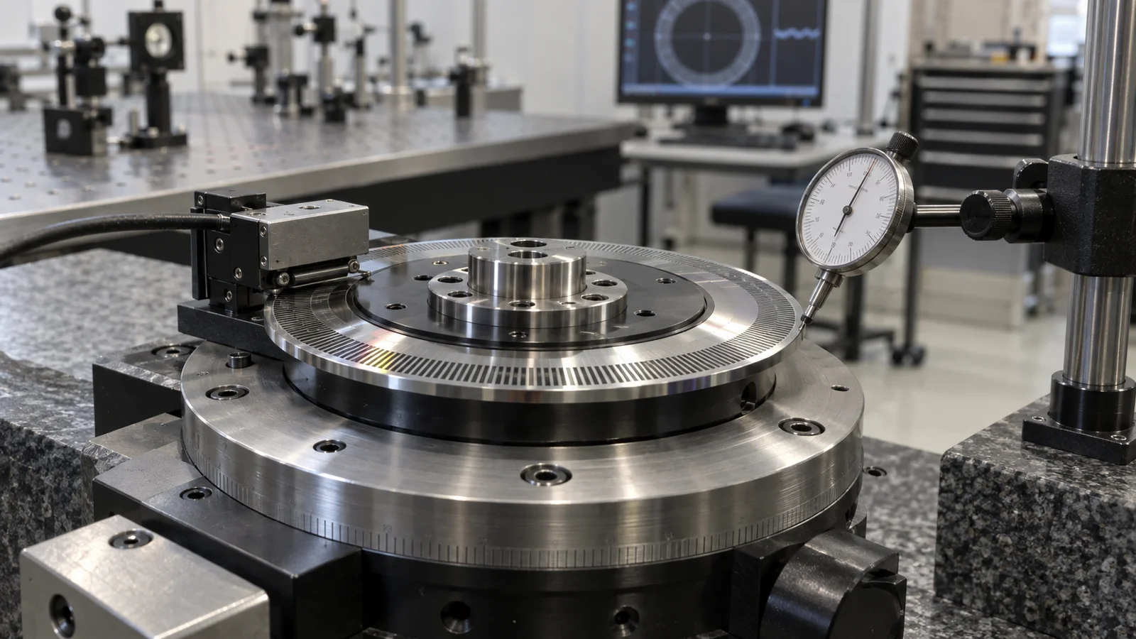
Specify a permitted temperature band over the operating day together with a maximum rate of change per hour and an allowable vertical gradient, measured at tool height with the room systems running.
TECHNOLOGY / SYSTEM INTEGRATION
A direct-write tool is a metrology instrument wearing a process costume. This guide sets out the temperature stability, floor vibration, cleanliness, airflow and power quality budgets to agree before delivery, plus the survey and acceptance measurements a buyer should own.
Published
DIRECT ANSWER
Agree five budgets and measure each one before the crate arrives. Temperature matters as stability, gradient and drift rate rather than as a setpoint, typically expressed as a permitted band over an operating day plus a maximum rate of change per hour. Floor vibration matters as a velocity criterion in the footprint the tool will occupy, commonly quoted as a VC class, measured with the room systems running. Cleanliness matters as airborne particle class plus airflow velocity across the write field. Power matters as voltage tolerance, frequency stability, harmonic distortion and a clean ground. Acoustics and EMC complete the list, because both reach the metrology through the structure and the cabling rather than through the recipe.
Ownership follows the budget. The supplier states what the tool requires in a site preparation guide; the buyer verifies that the room meets those numbers, corrects what is outside them and re-measures during process qualification. That means commissioning an independent vibration and temperature survey of the actual bay with HVAC, chillers, pumps and neighbouring equipment running, then documenting the results. If the site cannot comply, decide early whether to move the tool, isolate it on a dedicated foundation or rebuild the services of that bay. Retrofitting after installation is the most expensive version of this conversation.
ENGINEERING CONTEXT
Most direct-write systems are installed into rooms that already had a purpose. A spare corner of an existing cleanroom, a former metrology bay, a university laboratory with a raised floor and a shared chiller: each of these brings a set of disturbances that nobody measured because nobody needed to measure them before. Then the tool arrives and the symptoms are blamed on the tool. Overlay drifts over an eight-hour run, so the HVAC cycling above the write field becomes part of the investigation. CD uniformity steps every time the neighbouring pump starts, so power quality becomes part of the investigation. Focus loses lock for no reason that appears in the recipe, so floor vibration and acoustic pressure become part of the investigation. None of these are tool defects, and none can be negotiated away at acceptance, because the acceptance test is run in the buyer's room rather than the supplier's factory. The practical answer is to treat the site as the first process variable and to spend the survey money before the installation date rather than after.
Discuss your requirement ↗CRITICAL REQUIREMENTS
Specify a permitted temperature band over the operating day together with a maximum rate of change per hour and an allowable vertical gradient, measured at tool height with the room systems running.
Require a velocity criterion such as a stated VC class, verified at each foundation point with a calibrated survey under normal facility and neighbouring-equipment load.
Define airborne particle class for the tool bay plus the permitted airflow velocity and direction across the write field, including exhaust and heat load routing.
Fix voltage tolerance, frequency stability, harmonics, separate feed or conditioning, grounding resistance and EMC separation from noisy loads before ordering.
BUYER MATRIX
Give every shortlisted supplier the same process definition and request configuration-specific proof.
| Parameter | What to specify | Failure symptom in the tool | How it is verified |
|---|---|---|---|
| Temperature band and drift | Permitted band over the operating day, maximum rate of change per hour and allowable vertical gradient at tool height | Overlay and scale drift during long writes; slow loss of autofocus reference | Logged sensors at several heights over multiple days with the facility in normal operation |
| Floor vibration | Velocity criterion such as a stated VC class in the footprint, at the frequencies that affect the stage and column | Stage settling noise, image blur, stitching and overlay errors that vary with time of day | Calibrated velocity survey at each foundation point with all equipment running |
| Cleanliness and airflow | Airborne particle class for the bay, plus permitted airflow velocity and direction across the write field | Local defects and particles appearing in patterned areas; unstable metrology measurements | Particle counting and anemometer readings mapped across the tool envelope |
| Power quality | Voltage tolerance, frequency stability, harmonic distortion limit, ride-through behaviour and separate feed | Unexplained system restarts, dose instability, damaged drives during facility events | Power quality analyser logging during a representative production week |
| Grounding and EMC | Grounding resistance target, dedicated clean ground, segregated trays and distance from variable-frequency drives | Position jitter, communication errors, intermittent faults that follow other machines | Ground resistance test plus EMC walkthrough of cable routing and bonding |
| Acoustics and structure-borne noise | Maximum sound pressure at the tool and separation from plant, fans and traffic routes | Focus instability and increased settling time during high-exposure runs | Sound level mapping with the building in normal daytime operation |
A maskless lithography system writes features by moving either the substrate or the optical head through a long sequence of precisely located exposures. Every one of those locations is established by a metrology frame, a stage, an interferometer or encoder reference and an autofocus loop, all of which respond to the room. Overlay and linewidth are therefore process results and site results at the same time, which is why an acceptance figure quoted for a factory environment cannot be assumed to transfer to a busy laboratory without evidence.
Treating the site as a process variable changes the order of work. Instead of asking whether the tool meets specification in isolation, the buyer defines what the room must deliver, verifies it, and only then runs the process acceptance. That sequencing also gives a clean diagnosis later: when the room is characterised before installation, any drift observed afterwards can be attributed to a known variable instead of argued over. It also protects the schedule, because the remediation options worth taking are rarely available after the crate is on the dock.
Absolute room temperature is the least interesting number in the requirement. What moves a precision tool is change: drift over an operating day, gradients between floor and structure, and rate of change when the HVAC cycles or occupancy shifts. A room held within 1 °C over the day with slow monotonic drift often supports overlay better than one nominally within 0.5 °C that swings every hour, because a steady offset can be calibrated out while cyclic disturbance usually cannot.
Practical points follow from that. Place sensors where the tool will sit, at several heights, not only at the wall thermostat. Run the recording long enough to include nights, weekends and the neighbouring processes that load the same air handling unit. Route supply diffusers away from the write field, and keep heat sources such as chillers, pumps and bake plates out of the same return path. Finally, decide what warm-up means: the tool's own thermal mass needs documented stabilisation time after power-up before any qualification data is taken, and that time belongs in the recipe and the shift plan.
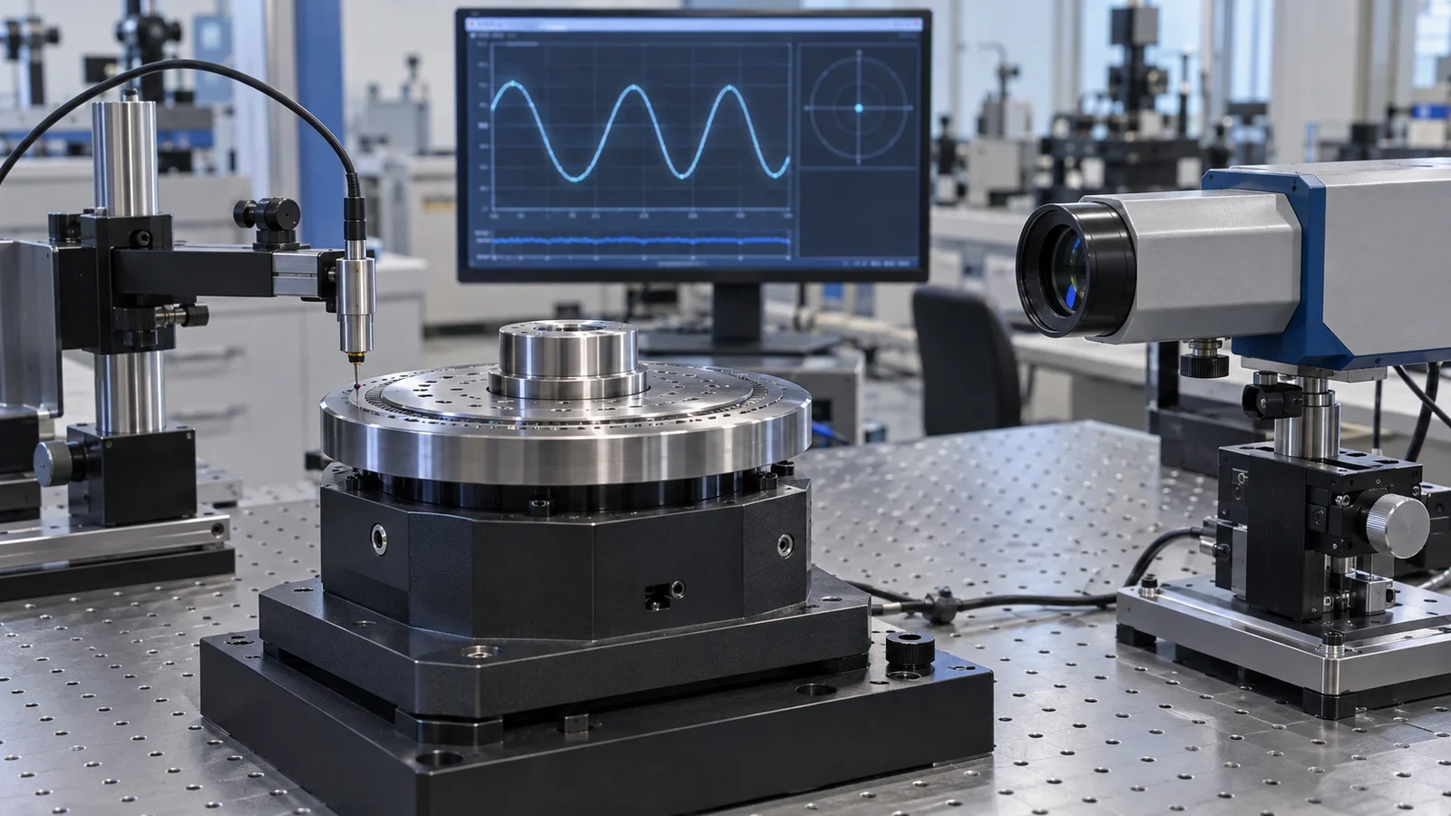
Vibration requirements are commonly expressed as velocity criteria with classes such as VC-A through VC-G, quoted over a defined frequency band. The important detail is where the measurement applies. A survey taken in the middle of an empty room says nothing about the bay next to a pump, a lift shaft, a loading dock or a busy corridor, and nothing about the floor slab over a mezzanine or a raised access floor. Require the survey at each foundation point of the actual tool footprint, with the building systems, neighbouring tools and normal daytime traffic running.
When the site fails, the remedies differ in cost and in what they actually fix. Moving the tool to another bay is cheap if the building has options. A dedicated inertia base or isolation platform handles structure-borne input but adds height, weight and load path questions that the floor must be evaluated for. Changing damper settings or relocating equipment often costs less than expected and also improves temperature behaviour. What never works is discovering the problem during process qualification and negotiating the tool through it.
Airborne cleanliness is the easiest parameter to argue about and least often the real cause, because a tool already sitting in a classified room tends to stay clean. The useful question is airflow. High velocity air across the write field disturbs the substrate, the stage thermal boundary and the focus loop, and can turn a very clean room into a poor process environment. Specify not just particle class but permitted velocity and direction across the tool envelope, including local returns, filter unit placement and the exhaust from neighbouring wet equipment.
Acoustics are usually forgotten entirely until they appear as unexplained focus noise. Sound pressure couples into the column and the substrate, and the resulting motion looks identical to focus loop instability in process data. Treat it as a real line item: keep the tool away from high-level sources, avoid placing it directly beneath plant rooms or heavily trafficked routes, and measure during normal daytime operation rather than at night.
Electrical requirements belong in the same early conversation. Voltage tolerance, frequency stability, harmonic distortion and ride-through behaviour all vary between a university building, an industrial park unit and a mature fab, and all affect drives, metrology electronics and the control computer differently. A dedicated feed, appropriately sized conditioning, documented harmonic limits and a clean low-impedance ground are far cheaper to install while walls are open than to add later. Ask the supplier for the power line input requirements in the site preparation guide and compare them honestly with what the building can deliver.
Grounding and EMC deserve their own walkthrough. Segregate encoder and metrology cabling from variable-frequency drives, welders, RF generators and high-current returns, keep cable trays physically separated and bonded correctly, and agree the grounding scheme before contractors leave site. Random resets or jitter that correlates with another machine starting are almost always routing or bonding problems, and they are diagnosed far more easily from an agreed drawing than from a symptom described over the phone.
The sequence that works is survey, remediate, re-survey, install, then re-measure during process qualification and periodically afterwards. The buyer owns the first three steps, since only the buyer controls the building. The supplier owns the installation conditions and should confirm them explicitly rather than proceeding on assumption. Both parties benefit from writing the environmental conditions into the acceptance document, since a demonstration run outside those conditions proves little about production behaviour.
Practical due diligence is mostly documentation. Collect the floor plan with the tool footprint and service clearances, the structural drawing showing slab and loading, the HVAC drawing with diffuser and return positions, the single-line power drawing, the list of neighbouring equipment and duty cycles, and any existing vibration or particle records. Send those with the enquiry and ask for the site preparation response in writing. A supplier serious about the installation will ask about the room before quoting; that attention is one of the more reliable signals available during selection.
CONCLUSION
No amount of machine capability survives a site that was never characterised. Agree the five budgets before the purchase order, measure them in the actual bay under real facility load, fix what is outside them, and repeat the measurement as part of acceptance and periodic qualification. Buyers who sequence it that way spend their commissioning time on process learning, and buyers who skip it spend the same time explaining why a very good tool produces mediocre data.
EVIDENCE CHECKLIST
FAQ
Temperature uniformity and drift, followed closely by floor vibration in shared laboratory buildings. Vibration problems usually reflect siting mistakes: tools placed next to pumps, corridors, lift shafts or mezzanine floors that were never surveyed before installation.
The requirement depends on the process and the tool configuration. Many R&D systems are installed in classified bays rather than a complete fab, but the local cleanliness, airflow across the write field and heat load routing still need agreed values from the site preparation guide.
You can and should run an initial check, but fit-for-purpose instruments must be calibrated and set up correctly. A professional survey with proper mounting conditions and long enough sample windows gives data the supplier can act on.
Usually the buyer, because the building is the buyer's scope. This is exactly why the survey and any remediation should be completed before the installation date is fixed rather than negotiated afterwards.
Floor plan with tool footprint and service clearances, structural slab loading, HVAC diffuser and return layout, single-line power drawing, neighbouring equipment and duty cycles, plus any existing particle or vibration records.
AUTHORITATIVE SOURCES
TECHNICAL REVIEW
Send the application, critical parameters and any drawing or process information available.
Discuss your application ↗