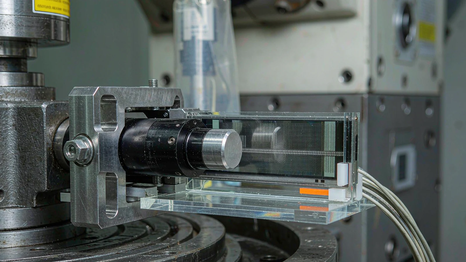
Optical Encoder Vibration and Shock Survival Testing: How to Read IEC 60068 Evidence and Choose a Feedback Device That Lasts
Optical encoders fail in service far more often from installation resonance and mounting dynamics than from the vibration levels printed on a datasheet. This guide explains what IEC 60068-type sine, random and shock tests actually prove, how to read a supplier test report, where resonant amplification appears in real machine structures, and exactly which evidence to request before qualifying a linear or rotary encoder.
Published
DIRECT ANSWER
What should a buyer prioritize?
A vibration or shock rating tells you that a sample survived a defined laboratory input on a defined fixture. It does not tell you that the encoder will survive your machine, because the input your encoder actually sees is shaped by the mounting structure between the shaker table and the readhead. Qualify the installation, not just the device.
Practically, ask the supplier for four things: the standard and test clause used (for example IEC 60068-2-6 sine, IEC 60068-2-64 random, IEC 60068-2-27 shock), the full parameter set behind the headline number (frequency range, amplitude, duration, axes, mounting fixture), a functional criterion that is more demanding than 'no mechanical damage' (signal amplitude, error counters, interpolation margin before and after), and the resonant-frequency behavior of the scale and readhead assembly itself. Then repeat the critical part on your own machine: measure the acceleration at the readhead location during real duty cycles and compare it with the tested envelope.
ENGINEERING CONTEXT
The decision starts with the real constraint.
Most encoder vibration failures are not caused by the encoder exceeding a published limit. They are caused by the bracket, the scale backing, the cover or the cable clamp forming a resonant structure that amplifies a modest machine input into a large local one. A datasheet that says 20 g shock resistance says nothing about a 340 Hz bracket mode that turns 2 g of spindle-induced excitation into 18 g at the readhead. Because the resulting faults are intermittent and load-dependent, teams chase electrical noise, replace readheads that test clean on the bench, and never measure the mechanical transfer function. The fix is to treat vibration qualification as a two-part problem: a documented laboratory envelope for the device, and a measured mechanical response for the installation.
Measure or estimate acceleration at the encoder mounting location across the operating frequency range, including idle, cutting or scanning duty, acceleration ramps and any incidental impact events such as tool change, wafer handoff or door closing.
02
Map the mechanical transfer path
Identify every element between the excitation source and the encoder: bracket geometry, scale backing, covers, fastener spacing, cable clamping and strain relief. Each one contributes stiffness and mass, and therefore resonant modes.
03
Demand complete test parameters
Accept no vibration claim without standard clause, frequency range, amplitude, sweep rate or duration, number of axes, mounting fixture description, sample count and a stated functional acceptance criterion measured before and after.
04
Qualify the assembly, not the part
Test or simulate the encoder together with its production bracket, scale mounting and cable routing, then re-baseline signal margin after commissioning so that mechanical degradation becomes measurable over time.
BUYER MATRIX
Compare evidence, not feature labels.
Give every shortlisted supplier the same process definition and request configuration-specific proof.
Common IEC 60068 environmental test clauses used for encoder qualification and what each one actually demonstrates
Test clause
Input applied
What a pass demonstrates
What it does not demonstrate
IEC 60068-2-6 (sine vibration)
Sinusoidal sweep across a stated frequency range at controlled displacement or acceleration amplitude, typically in three orthogonal axes
The device survives a defined steady sinusoidal input and can often reveal resonant frequencies when the response is monitored during the sweep
Behaviour under simultaneous broadband excitation, long-duration fatigue accumulation, or any specific bracket geometry other than the fixture used
IEC 60068-2-64 (random vibration)
Broadband random excitation defined by an acceleration spectral density profile over a stated duration and axis set
The device survives statistically distributed multi-frequency loading, which is closer to real transport and machine environments
Response at a single structural resonance, shock events, or the effect of a compliant bracket that was not part of the test fixture
IEC 60068-2-27 (mechanical shock)
Defined half-sine or similar pulses of stated peak acceleration and duration, a stated number of pulses per direction
The device survives discrete impact events such as drops, hard stops, collisions or handling incidents
Fatigue from continuous vibration, resonant amplification, or cumulative damage from millions of low-level cycles
IEC 60068-2-64 plus resonance search
Low-level broadband or sine excitation with response monitoring to identify natural frequencies of the assembly
The resonant frequencies of the encoder and its mounting are known and can be compared against the machine's excitation spectrum
Anything about survival on its own; the value is diagnostic and feeds back into mechanical design
What vibration and shock testing actually proves
Environmental test standards exist to make a statement reproducible. The IEC 60068 series defines how to apply mechanical stress in a laboratory so that two parties can compare results without arguing about method. When a supplier states that an encoder passes a vibration test, the meaningful part is not the headline number but the clause and parameter set behind it. IEC 60068-2-6 applies a sinusoidal sweep and is useful for locating resonances. IEC 60068-2-64 applies broadband random excitation defined by an acceleration spectral density profile and better represents transport and running machinery. IEC 60068-2-27 applies discrete shock pulses and represents impacts, hard stops and handling incidents. These three answer different questions and are not interchangeable.
Two further qualifiers decide how much weight a test report deserves. The first is the acceptance criterion. A pass that only means the housing did not crack is far weaker than a pass that requires the device to remain functionally within specification during and after the test: signal amplitude inside limits, no count errors, no alarm flags, unchanged interpolation margin. Optical encoders are measuring instruments, so the functional criterion is the one that matters. The second qualifier is the fixture. A readhead bolted directly to a rigid shaker armature experiences a very different input from the same readhead on a tall bracket with a cable pulling on one side. Unless the report describes the fixture, the test describes an assembly you do not have.
A useful way to think about this is that the test certifies a sample, while the machine certifies the installation. Standards give you comparable evidence about the sample. Only measurement on the machine tells you whether the local input stayed inside the tested envelope.
Installation resonance: the failure mode no datasheet covers
Every mechanical path between an excitation source and an encoder has mass and compliance, and therefore natural frequencies. A scale bonded to a thin backing, a readhead on a cantilevered bracket, a protective cover with long unsupported spans, and a cable clamped only at one end all add modes. When a machine's excitation coincides with one of these modes, the local acceleration at the readhead can be many times the acceleration measured at the machine frame. This is why two identical encoders on identical machines can behave completely differently after a bracket revision, and why a device that passed a 10 g laboratory test can fail under a machine that only produces 1 g at its base.
The practical consequences for an optical encoder are specific. Readhead-to-scale gap modulation changes signal amplitude and therefore interpolation margin, which shows up as position jitter rather than a hard fault. Relative motion between the readhead and the scale at a frequency the servo cannot track introduces apparent position noise that the controller tries to follow, adding current ripple, audible noise and heat. Repeated flexing at the cable exit works the strain relief and can fatigue individual conductors, producing intermittent errors that correlate with axis motion but not with position. None of these present as 'vibration damage'; they present as signal quality problems, which is why mechanical causes are so often missed.
Diagnosing resonance is straightforward once you look for it. With the machine running its normal duty cycle, place an accelerometer as close to the readhead as possible and record the spectrum. Compare it with a reference measurement on the machine frame. Peaks that appear only at the readhead are structural modes in the mounting path. A second check is to sweep the axis slowly through its speed range while monitoring signal amplitude: a speed at which amplitude collapses or error counters spike usually corresponds to a mechanical resonance being excited by the motion profile rather than to an electrical bandwidth limit.
Mechanical design responses that remove resonances
The remedy is almost always stiffness and mass distribution rather than a more rugged encoder. In rough order of effectiveness:
Shorten and thicken the readhead bracket; raise its first natural frequency above the highest significant excitation frequency
Support the scale along its full length on a continuous, flat, stiff backing rather than at intermittent mounting points
Clamp the cable close to the readhead so cable mass and motion do not load the optical head, and again at a fixed point before any moving segment
Avoid long unsupported cover spans and add stiffening or intermediate support where a cover is part of the structure
Separate the encoder mounting from impact-prone structures such as doors, guards, tool changers and pneumatic actuators
Where isolation is unavoidable, isolate the whole assembly consistently so that relative motion between scale and readhead stays small
A qualification request should be specific enough that a vague answer is visibly incomplete. Ask for the standard and clause, not just a g value. Ask for the frequency range and amplitude, the number of axes, the duration or number of sweep cycles, the mounting fixture used, the sample count, and whether the samples were operating and monitored during the test. Ask whether the reported figure applies to the readhead, the scale, or the complete assembly, because those are different objects with different masses and different mounting conditions. Ask for the criterion: what was measured, at what limits, before and after.
Then ask two questions that separate a marketing summary from engineering evidence. First, what were the observed resonant frequencies, and how were they identified? A supplier that has done a resonance search can tell you where not to excite the device, which is far more useful than a survival number. Second, was the device powered and functionally verified during the exposure? An unpowered sample proves structural survival; a monitored sample proves measurement integrity. For optical encoders, measurement integrity is the requirement.
It is also reasonable to ask how the test relates to the intended duty. Transport vibration, machine-tool cutting excitation, wafer-handling impacts and stage acceleration ramps produce very different spectra. A supplier who asks which of those applies before quoting a test result is doing real engineering. SENFU application engineering works in this direction: send the axis geometry, mounting concept, duty cycle and measured or estimated spectrum, and the review returns a configuration recommendation plus the specific test evidence relevant to that configuration rather than a generic environmental claim.
The qualification closes with a measurement on the real machine. Define an acceptance record at commissioning that includes the acceleration spectrum at the readhead under representative duty, the encoder signal amplitude and error counters, and photographs of the bracket, scale mounting and cable clamping. Repeat the spectrum measurement after any mechanical revision, and sample the signal baseline at planned maintenance intervals. A slow decline in signal margin accompanied by a change in the measured spectrum points at a mechanical cause; a decline with a stable spectrum points at contamination or optics, which is a different problem with a different remedy.
Set acceptance limits before the machine ships rather than after a fault appears. A reasonable starting point is that the encoder's signal amplitude must remain inside the supplier's specified operating window under the worst measured duty, with margin, and that no error counter increments occur during a defined production period. Where the measured spectrum has energy near a known mode of the assembly, change the mechanics before accepting the machine: raising a bracket's stiffness at the design stage costs far less than diagnosing intermittent position errors after delivery.
This approach converts vibration qualification from a paperwork exercise into an engineering control. The laboratory test evidence from the supplier establishes what the device can withstand. The measurement on your machine establishes what it is actually asked to withstand. The gap between the two is where failures live, and it is the only part of the problem that the machine builder can control.
Vibration and shock ratings are useful filters, but they certify a sample on a fixture. Service reliability is decided by the mechanical path between the excitation source and the readhead: bracket stiffness, scale support, cover spans and cable clamping. Resonant amplification in that path, not the published g value, is what most often produces intermittent encoder faults.
To qualify a SENFU encoder for a demanding axis, send the mounting drawing, duty cycle, acceleration or spectrum data at the encoder location, and the candidate configuration. SENFU application engineering can confirm the relevant IEC 60068-type test evidence, identify mechanical risks in the mounting concept, and define the commissioning baselines that make later mechanical degradation measurable instead of mysterious.
Standard and clause of every vibration or shock test cited, with full parameter set (range, amplitude, duration, axes)
Description of the test fixture and whether samples were powered and functionally monitored during exposure
Resonant frequencies identified for the readhead, scale and complete assembly
Acceleration spectrum measured at the readhead location under representative machine duty
Signal amplitude and error-counter baseline at commissioning with scheduled re-inspection and acceptance limits
FAQ
Questions engineers ask before selection.
What is the difference between IEC 60068-2-6, -2-64 and -2-27 for an encoder?
IEC 60068-2-6 applies a sinusoidal frequency sweep and is best for finding resonances. IEC 60068-2-64 applies broadband random vibration defined by an acceleration spectral density profile and better represents running machinery and transport. IEC 60068-2-27 applies discrete shock pulses and covers impacts, hard stops and handling. A claim should name the clause, because a shock rating says nothing about vibration fatigue.
Why does an encoder rated for 20 g fail on a machine that only produces 2 g?
Because the rating applies to the device on a fixture, while the readhead sits at the end of a mechanical path with mass and compliance. If a natural frequency of that path matches an excitation frequency present in the machine, the local acceleration at the readhead can be several times the acceleration at the machine frame. Measure at the readhead, not at the base.
Should the encoder be powered and monitored during vibration testing?
Yes. An unpowered sample only proves the housing does not break; a powered, monitored sample proves that signal amplitude, interpolation margin and error counters stay inside specification during exposure, which is what a motion axis requires. Ask whether functional monitoring was part of the test and what limits were applied.
What are the typical symptoms of a resonance-driven encoder problem?
They usually look electrical: position jitter that varies with speed, signal amplitude that collapses at particular speeds or operations, error counters that increment only under a specific duty cycle, and servo current ripple at a structural frequency. Measuring the acceleration spectrum at the readhead while the symptom is present confirms the cause quickly.
How do I make an encoder mounting less sensitive to vibration?
Add stiffness and remove cantilevers: shorten and thicken the readhead bracket, support the scale continuously on a flat stiff backing, clamp the cable close to the readhead so its mass does not load the optical head, and support long cover spans. If isolation is used, apply it consistently so relative motion stays small.
What should I send a supplier for a vibration qualification review?
Send the axis geometry and mounting drawing, the scale and readhead mounting concept, the duty cycle with maximum velocity and acceleration, any measured acceleration spectrum at the encoder location, the cable routing and clamping, and the candidate model. With those inputs the relevant IEC 60068-type evidence and the mechanical risks can be stated.