
Define the harmonic budget
Allocate an allowable first-harmonic amplitude in arc seconds, then convert it to a radial offset allowance at the actual reading radius instead of working with micrometres alone.
TECHNOLOGY / ANGULAR METROLOGY
Eccentricity between the grating axis and the rotation axis is the dominant first-harmonic error in angular encoders. This guide explains where it comes from, how to recognise it in an error record, how to measure and separate it, and how to budget mount, coupling and bearing contributions.
Published
DIRECT ANSWER
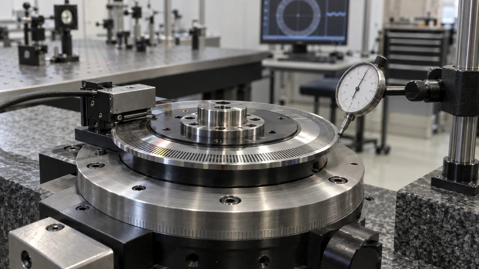
Axis eccentricity is the offset between the centre of the encoder's grating pattern and the axis the assembly actually rotates about. It converts into an angular error with amplitude equal to the offset divided by the radius at which the pattern is read, so the same physical offset produces a much larger error on a small-diameter disc than on a large one. On the error record it appears as a clean first harmonic: one sine cycle per revolution, with a stable amplitude and a stable phase relative to a shaft mark.
Because it is a pure geometric first harmonic, eccentricity is both predictable and largely removable. Measure the radial offset at the reading radius and convert it, separate it from bearing error motion with a reversal or multi-step method, then choose between three routes: improve the mounting datum, average it away with diametrically opposed readheads, or correct it in the controller with a harmonic table and verify the correction is stable over temperature and time. The one route that never works is ignoring it and hoping the accuracy class of the disc covers it.
ENGINEERING CONTEXT
Eccentricity is the most common reason a rotary axis misses its angular tolerance despite carrying a good encoder, and it is also the most misdiagnosed. The disc may be manufactured to a tight tolerance, but the eccentricity that matters is created at assembly: a bore-to-pattern offset, a shaft runout, a clamp that pulls the disc off centre as the screws are tightened, or a coupling that imposes a lateral load on the encoder's own bearing. The symptom looks like an encoder problem because the error repeats once per revolution with machine-like regularity, so the usual first response is to suspect the disc or the electronics. In most installations the disc is fine and the mounting loop is not. The difficulty is that a single indicator reading does not tell you which contribution you are looking at, because the indicator sees the sum of the pattern offset and the bearing error motion. Separating those two is the whole job, and it requires a method rather than a measurement.
Discuss your requirement ↗CRITICAL REQUIREMENTS
Allocate an allowable first-harmonic amplitude in arc seconds, then convert it to a radial offset allowance at the actual reading radius instead of working with micrometres alone.
Use the registration feature the manufacturer specifies, follow the clamp sequence and torque, and indicate the grating track or reference band rather than an arbitrary outer diameter.
Carry drive loads on the machine bearings and connect the encoder through a coupling that accepts residual misalignment without transmitting radial force or axial preload.
Use reversal, multi-step or dual-readhead methods to split mounting eccentricity from bearing error motion, because only the repeatable part can be corrected.
BUYER MATRIX
Give every shortlisted supplier the same process definition and request configuration-specific proof.
| Error source | Harmonic signature | How to detect it | Reduction route |
|---|---|---|---|
| Grating-to-axis eccentricity | First harmonic, one cycle per revolution, stable amplitude and phase | Radial indication at the reading radius plus a first-harmonic fit of the error record | Improve the mounting datum and clamp sequence, use opposed readheads, or apply a verified harmonic correction |
| Shaft and bearing error motion | Mostly at the first harmonic plus broadband content that does not repeat exactly between revolutions | Compare several revolutions and look at non-repeatable scatter; separate with reversal or multi-step methods | Improve the bearing and shaft, or isolate the encoder so it does not see the driven shaft's motion |
| Disc tilt and axial wobble | Gap modulation once per revolution leading to signal amplitude variation, with angle error content at the second harmonic | Signal amplitude versus angle record, plus a second-harmonic term in the error decomposition | Control the seating face squareness and the axial clamp, and keep the readhead gap inside its window |
| Graduation error of the disc | Higher harmonics tied to the line count and to the manufacturing process | Harmonic decomposition of a calibrated error record; amplitudes do not scale with mounting changes | Select a higher accuracy class or map and compensate the graduation error |
| Coupling-induced load | Error that appears or changes when the coupling is connected, often with a shifted phase | Measure with the coupling disconnected and connected, and compare the first harmonic | Use a coupling that accepts misalignment with low reaction force, and correct the alignment |
| Thermal and clamp drift | Slow change in the first-harmonic amplitude and phase over warm-up or after re-clamping | Repeat the harmonic fit after a thermal soak and after a clamp cycle | Control materials and torque, and re-verify the correction after any disturbance |
An angular encoder reports the angle between its grating pattern and its readhead. That report is only correct if the pattern rotates about the same axis the machine cares about. Eccentricity is the offset between those two axes. It has three common origins, and they stack. The disc itself may have a small offset between its mounting bore and its grating pattern. The shaft it is mounted on may run out relative to its own bearings. And the assembly process may introduce offset that neither part had, typically because a clamp ring or a set of screws pulls the disc sideways as it is tightened.
The third origin is the one that surprises people, because it is created during assembly and disappears when the disc is removed and re-indicated. It is also the one that responds immediately to procedure: a specified clamp sequence, an even torque progression, and an indication taken on the reference band during tightening rather than afterwards. A disc that measures well on a bench and badly in the machine has usually been installed rather than manufactured into its error.
Eccentricity produces a sinusoidal angular error with one cycle per revolution. The amplitude is simply the offset divided by the radius at which the pattern is read. In angular terms that is the offset ratio times 206265 to reach arc seconds. A five micrometre offset read at a fifty millimetre radius gives an amplitude of roughly twenty arc seconds; read at a twenty millimetre radius the same offset becomes roughly fifty arc seconds. This is why small-diameter rotary encoders are far more sensitive to mounting quality than large-diameter ring encoders, and why a resolution or accuracy class quoted without a mounting allowance is incomplete.
Two features make the signature recognisable. The amplitude and the phase are stable from revolution to revolution, and the error returns exactly when the shaft returns to the same angular position relative to a mark. Bearing error motion, by contrast, contains content that does not repeat exactly between revolutions. Disc tilt and axial wobble modulate the readhead gap once per revolution, which appears first as signal amplitude variation and then, through the interpolator, as error content at the second harmonic. Graduation error appears at higher harmonics tied to the line count. Decomposing an error record into harmonics is therefore the fastest diagnostic step available: the harmonic number tells you which physical mechanism to go and fix.
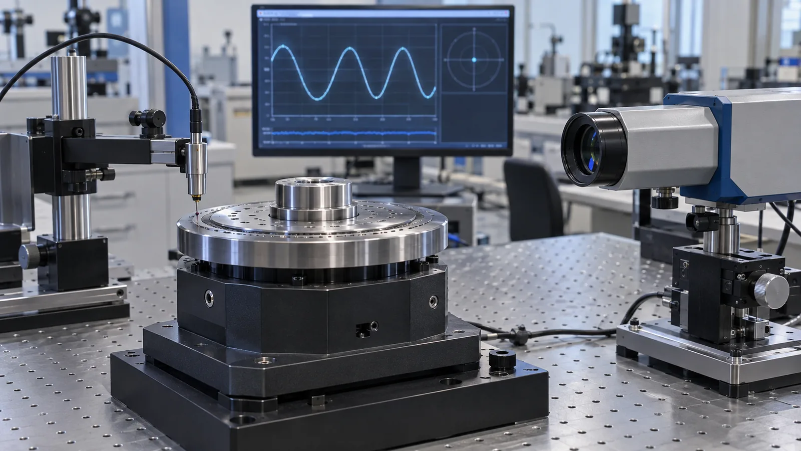
A dial or capacitive indicator placed on the grating track gives the total radial deviation, which is the sum of the pattern offset and the spindle error motion. Useful, but not sufficient: it cannot tell you which part is correctable. The standard way to split them is a reversal or multi-step error separation. In its simplest form the artifact is measured, rotated by a fixed increment relative to the spindle, and measured again. Because the spindle contribution stays fixed in space while the artifact contribution rotates with the part, the two can be separated arithmetically.
For an encoder already installed on a machine, the practical alternative is to compare it against an independent angular reference. A calibrated indexing table, an autocollimator with a precision polygon, or a second encoder of known quality can provide reference angles at a set of positions around the revolution. Take readings in both directions, subtract the reference, plot the residual against angle, and fit the harmonics. Then repeat the whole sequence and check whether the first-harmonic amplitude and phase reproduce. Reproducible content is correctable; non-reproducible content is bearing behaviour and must be fixed mechanically.
Mount on the datum the encoder manufacturer specifies and nowhere else. Registered or tapered bores, clamp rings and specified seating faces exist precisely because the grating pattern is referenced to them. Indicating the outside diameter of a hub and assuming it is concentric to the pattern is the single most common assembly error in rotary feedback. Indicate the grating track itself, or the reference band the manufacturer nominates, while the clamp is tightened in the specified sequence.
Then keep load out of the encoder. A rigid coupling between a driven shaft and an encoder shaft creates a statically indeterminate loop: the encoder's own bearing fights the machine bearing, and the resulting lateral force is a permanent eccentricity that no amount of disc accuracy will remove. Use a coupling designed to accept angular and radial misalignment with low reaction force, check its wind-up and hysteresis against the servo requirement, and align the two shafts properly rather than relying on the coupling to absorb a large offset. Also confirm that axial preload, thermal growth of the shaft and cable strain do not push on the assembly once it is closed up.
Work in arc seconds and then convert. Start with the angular tolerance at the point of interest, allocate a share to the first harmonic, and convert that share into a radial allowance at the reading radius using the offset-over-radius relationship. This gives the assembly team a number they can measure with an indicator, which is far more useful than an arc-second target they cannot see. Split the remainder between graduation error, bearing error motion and thermal drift, and give each a verification method.
Then decide the correction strategy deliberately. Two diametrically opposed readheads average out odd harmonics, including eccentricity, which is why that architecture is common where the budget is tight; it leaves even harmonics untouched, so it is not a substitute for good mounting. A controller-side harmonic correction can remove the residual first harmonic, but only the repeatable part, and only as long as the correction stays valid. Verify any correction after a thermal soak, after a clamp cycle and after transport, and record the harmonic fit at acceptance so drift later has a baseline to be compared against.
Ask for the eccentricity relationship for the specific model in a form you can use: the reading radius, the stated eccentricity tolerance or its equivalent angular consequence, the specified mounting datum and clamp procedure, the recommended coupling interface with its allowable misalignment and transmitted load, and the readhead gap window. Ask whether the accuracy figure quoted assumes a single readhead or an opposed pair, because the two are not comparable.
At acceptance, require an error-versus-angle record with harmonic amplitudes, a radial indication of the grating track converted to arc seconds, a repeatability check across at least two revolutions and two directions, and a signal amplitude record over the revolution. If a harmonic correction has been applied, require the correction table and the conditions under which it was derived. Suppliers who supply the encoder as part of a defined mechanical interface can usually provide the mounting drawing and the procedure together, which closes the gap between a good disc and a good installation.
CONCLUSION
Eccentricity is not a defect in the encoder, it is a property of the installation, and it is one of the few precision errors that can be predicted with simple arithmetic before anything is built. Convert the angular budget into a radial allowance at the reading radius, mount on the specified datum, keep the coupling from loading the encoder, and verify the result with a harmonic decomposition rather than a single indicator reading. Rotary axes treated this way hold their first-harmonic budget; those treated as a catalogue selection problem usually discover the eccentricity at acceptance, when it is expensive to move.
EVIDENCE CHECKLIST
FAQ
Divide the offset by the radius at which the grating is read to get the error in radians, then multiply by 206265 for arc seconds. The same offset produces a larger angular error on a smaller reading radius, which is why small rotary encoders are more sensitive to mounting quality.
Eccentricity is repeatable: the same amplitude and phase return every revolution. Bearing error motion contains content that does not repeat exactly. Compare several revolutions, or use a reversal or multi-step method to separate the two contributions arithmetically.
They cancel odd harmonics, including the first-harmonic eccentricity term, because the two readings are taken half a revolution apart. Even harmonics remain, so opposed readheads reduce eccentricity but do not replace good mounting and alignment practice.
It removes the repeatable part of the first harmonic and nothing else. It is reliable only if the correction remains valid, so it must be re-verified after thermal soak, re-clamping and transport, and the harmonic fit should be recorded at acceptance as a baseline.
Usually because the error is created during assembly or by the coupling. Indicating an arbitrary outer diameter instead of the grating track, an uneven clamp sequence, or a rigid coupling transmitting lateral load will all introduce eccentricity that the disc itself never had.
AUTHORITATIVE SOURCES
TECHNICAL REVIEW
Send the application, critical parameters and any drawing or process information available.
Discuss your application ↗