
Oil-free pumping path
No oil-sealed mechanical pump may back the column or chamber, even intermittently; dry scroll or diaphragm backing for turbomolecular and ion pumps, with venting done using dry nitrogen or filtered air.
TECHNOLOGY / E-BEAM LITHOGRAPHY VACUUM PRACTICE
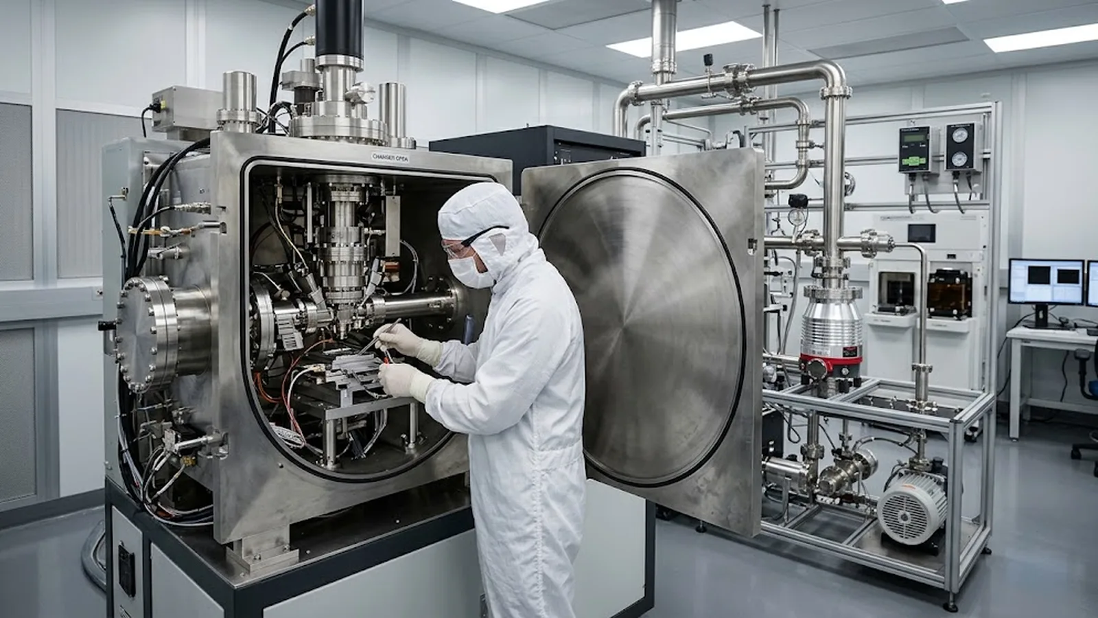
In electron-beam lithography the vacuum path is a precision component. Hydrocarbons and other volatiles that reach the column and the wafer chamber crack under the electron beam and deposit as carbon where the beam is smallest, degrading current stability, spot quality, and critical dimensions over time. This guide traces contamination sources through the vacuum path, explains how beam-induced deposition manifests in lithography results, and lays out the pumping, materials, and operational controls that keep a writing system clean for the long term.
Published
DIRECT ANSWER
Vacuum path contamination in electron-beam lithography is the presence of condensable molecules—mainly hydrocarbons from pump oil backstreaming, elastomer outgassing, fingerprints, and resist residues—that migrate into the beam path and the wafer chamber. Wherever the beam dwells on a surface, these molecules crack and polymerize into a hard carbonaceous film, so the contamination concentrates exactly where the machine is most sensitive: apertures, the final lens pole piece, alignment marks, and the resist surface itself.
The lithography symptoms are progressive: beam current that drifts and calibrations that do not hold, growing astigmatism and spot size, alignment marks that lose contrast as they carbonize, and critical dimensions that widen shot by shot as deposition builds on the writing surface. Control rests on four pillars—oil-free pumping with a clean backing train, differential pumping and clean apertures that protect the column, material discipline in everything the vacuum sees, and scheduled cleaning plus contamination-rate monitoring so the machine's cleanliness becomes a measured, budgeted quantity rather than an impression.
ENGINEERING CONTEXT
A dedicated e-beam lithography system spends its life with a resist-coated wafer inches from a hot filament and a field-emission tip, in a chamber that is cycled to atmosphere hundreds of times a year. Every pumpdown brings in water, solvents from the resist bake, and whatever the operator's gloves transferred to the sample holder. The result is a slow, invisible degradation: hydrocarbon partial pressures far below what any pressure gauge registers as a problem still deliver enough molecules to the beam-exposed surfaces to grow carbon at nanometers per hour. The insidious part is that the machine never fails outright—dose calibration quietly needs more frequent refresh, focus and stigmation drift faster, mark-detection thresholds creep upward, and linewidth measurements widen. Teams often chase these symptoms through filament changes, alignment retries, and resist process requalification, spending weeks on the electro-optics while the actual cause is a chamber that has become a hydrocarbon reservoir. Because contamination effects accumulate over weeks and masquerade as normal drift, they are among the last suspects examined and among the cheapest to fix once measured.
Discuss your requirement ↗CRITICAL REQUIREMENTS
No oil-sealed mechanical pump may back the column or chamber, even intermittently; dry scroll or diaphragm backing for turbomolecular and ion pumps, with venting done using dry nitrogen or filtered air.
Differential pumping between the electron gun and the chamber, clean beam-defining apertures with defined replacement intervals, and a column vacuum that stays in its specified range while the chamber is cycled.
Every outgassing contribution accounted for: low-vapor-pressure elastomers or metal seals, documented cable and stage materials, no unqualified greases or adhesives, and handlers using solvent-cleaned tools and cleanroom gloves.
A quantitative contamination-rate test performed at commissioning and on a periodic schedule, with an acceptance threshold that triggers cleaning before lithography results degrade.
BUYER MATRIX
Give every shortlisted supplier the same process definition and request configuration-specific proof.
| Aspect | Oil-free pumping (dry backing, ion/turbo) | Differential pumping + clean apertures | Cold trap / cryopanel | Plasma or UV cleaning cycles |
|---|---|---|---|---|
| What it addresses | Removes the largest chronic hydrocarbon source: backstreaming pump oil and its vapor transport into the column | Protects the gun and column from chamber-borne volatiles during cycling and from process vapors at the wafer | Pumps condensables (water, solvents) quickly, shortening pumpdown and reducing the volatile inventory available to migrate | Actively removes already-deposited hydrocarbon films from chamber walls, holders, and fixtures |
| Where it acts | The entire pumping train, permanently | The beam line between gun, column, and chamber | Chamber walls and shroud surfaces during and after pumpdown | Chamber internals at scheduled intervals |
| Typical limits | Requires disciplined venting practice; a single oil-pump session can undo months of cleanliness | Apertures themselves contaminate and need scheduled replacement or cleaning | Cryosurfaces regenerate and can shed condensed load when warmed; adds complexity and consumables | Does nothing for ongoing sources; ozone/plasma species must be chosen to avoid damaging sensitive components |
| Verification method | RGA spectrum showing no pump-oil fragmentation pattern; clean pumping schematic on file | Column vacuum stability during chamber cycling; aperture inspection or replacement log | Pumpdown time curves from vent to operating pressure | Contamination-rate test before and after cleaning, showing measurable reduction |
Contaminants reach the beam path by surface diffusion and by vapor-phase transport, not by bulk gas flow. A hydrocarbon molecule desorbing from an O-ring, a cable jacket, or a fingerprint on a sample holder hops across surfaces and, given enough residence time, arrives at any line-of-sight surface near the beam—including the final aperture, the pole piece, the wafer surface, and the alignment marks. The probability of arrival scales with the molecule's vapor pressure and the surface temperature, which is why a chamber that measures an acceptable total pressure can still be delivering a steady molecular flux of condensables to exactly the surfaces the beam touches.
The dominant sources in a lithography tool are well characterized: backstreaming from any oil-sealed pump in the backing chain, elastomer outgassing from door seals and cables, outgassing from freshly processed wafers and their resist, and direct transfer from handling—fingerprints deposit enough hydrocarbon to be visible in an electron microscope within minutes of exposure. Sample exchange is the recurring insult: every air exposure re-loads the chamber with water and brings new surface contamination in. A clean vacuum path is therefore less about one heroic design choice than about refusing every small source along the chain, because the beam integrates them all.
The electron beam cracks adsorbed hydrocarbons into a carbon-rich polymer that bonds to the surface, and this beam-induced deposition is self-focusing: it grows fastest where the beam dwells longest and where the current density is highest. In the column that means apertures thicken, edge sharpness degrades, and the spot quietly grows as scattered electrons from a contaminated aperture begin to dominate. On the wafer it means alignment marks and registration structures carbonize, lowering their detection contrast precisely where overlay accuracy depends on it.
The writing symptoms follow a recognizable progression. First, dose calibration intervals shorten as contaminated apertures and stray deposition change the effective beam current between checks. Next, focus and stigmation need correction more often and the corrected values drift rather than settle. Then mark detection degrades and overlay residuals rise on tools that mechanically have not changed. Finally, on the resist surface itself, deposition during exposure can contribute to linewidth growth and edge roughness, particularly on long, thin single-pass features where the beam dwells on freshly deposited material. Each symptom on its own invites a wrong diagnosis—an aging emitter, a resist problem, a stage issue—which is why a written contamination-rate record is the fastest way to include or exclude the vacuum path as the cause. Some artifacts of charged, degraded surfaces overlap with genuine charging effects, and separating the two is a standard part of the diagnostic sequence described in the [charging effect compensation guide](/technology/electron-beam-lithography-charging-effect-compensation-guide/).
The single most consequential decision is the pumping architecture: the column and chamber must be backed exclusively by dry pumps—scroll, diaphragm, or dry screw—with turbomolecular or ion pumps on the high-vacuum side, and the venting gas must be dry nitrogen rather than laboratory air. Diffusion-pumped systems and any shared oil-sealed roughing line are disqualified for e-beam lithography, because backstreaming oil finds the column regardless of baffles once the pump is warmed and the chamber at crossover pressure. The same discipline extends to every accessory: leaks checked with the same cleanliness standards, and no vacuum grease, tape, or adhesive inside the chamber unless its outgassing data is on file.
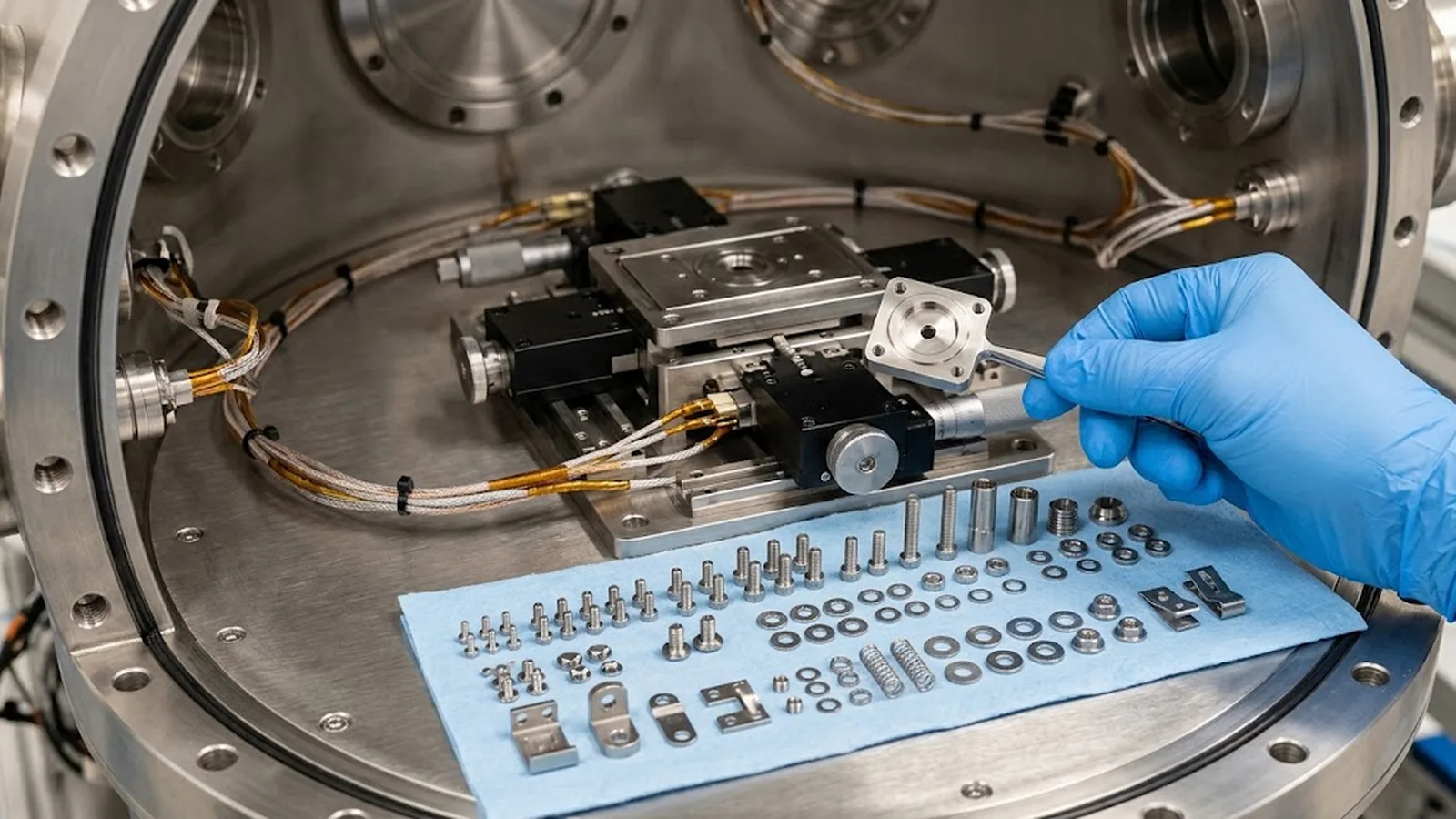
Everything that lives in the chamber is part of the vacuum path, including the motion system and its feedback. Stage components, cables, and encoder hardware inside vacuum-rated tools must be qualified as vacuum materials with measured outgassing and bakeout behavior, not merely tolerated; the qualification approach used for optical encoders in vacuum environments applies directly to any e-beam stage that carries its own metrology, as set out in the [optical encoder vacuum environment operation guide](/technology/optical-encoder-vacuum-environment-operation-guide/). The detail below shows the practical reality: a chamber interior where each element—holders, fasteners, sensor heads, cabling—has either a documented low-outgassing construction or a scheduled removal-and-clean interval.
Daily operation determines whether good hardware stays clean. Pumpdown should be staged so that water and solvent loads are removed before high voltage is applied, and beam-on time at standby should be minimized with the shutter closed and the beam blanked, because a hot, exposed gun is an effective pump for hydrocarbons. Samples should be cleanroom-gloved, solvent-rinsed where the process allows, and where possible vacuum-baked or plasma-cleaned before entry; a wafer fresh from a hotplate carries residual monomers that will distribute themselves across the chamber within the hour. Chamber doors should not stand open, spare flanges should be capped, and any part that was touched must be cleaned before it re-enters.
Scheduled active cleaning closes the loop. In-situ plasma cleaning (oxygen or argon/oxygen mixtures, tuned to avoid sputtering sensitive surfaces), UV-ozone exposure of removable parts, and periodic solvent wiping of chamber walls and sample holders remove the films that passive discipline cannot prevent. Fixtures and holders deserve particular attention because they sit closest to the beam and accumulate fastest; rotating two sets of holders—one in use, one freshly cleaned—keeps the schedule from colliding with production. For tools whose stages were qualified with outgassing and cleanliness evidence at acceptance, the same periodic re-check applied to the feedback hardware keeps the whole path consistent, following the pattern established in the [vacuum encoder outgassing qualification guide](/technology/vacuum-encoder-outgassing-qualification/).
A contamination-rate test converts cleanliness into a number. The classical method exposes a fresh silicon witness surface to a defocused, stationary beam of known current and current density for a fixed time, then measures the deposited film—by ellipsometry, AFM step height, or XPS—normalized to beam dose. Emission-system vendors and electron-microscope practice have converged on comparable figures of merit, and a lithography tool should hold itself to the same standard with a documented threshold: for example, a maximum film thickness per unit dose, verified at commissioning, after major service, and on a quarterly or semiannual schedule.
Residual gas analysis complements the rate test by identifying sources rather than effects: an RGA spectrum taken at operating pressure shows the characteristic fragmentation pattern of pump oil instantly, distinguishes water-dominated from hydrocarbon-dominated residual gas, and flags which elastomer or freshly installed part is outgassing. Together the two measurements support a qualification argument a buyer can audit: rate within specification, spectrum free of oil signatures, materials declarations on file, and a trend record showing that cleaning interventions restore the measured rate—demonstrating that the vacuum path is managed with the same rigor as the optics and the metrology chain. For systems where the chamber also hosts optical projection or chucking hardware, particle-side cleanliness requirements interact with molecular-side contamination control, and both belong in the acceptance documentation alongside the criteria described in vacuum chuck particle control practice.
CONCLUSION
Vacuum path contamination in e-beam lithography is not a breakdown that announces itself; it is a slow flux of condensable molecules that concentrates, under the beam, on exactly the surfaces the process depends on. Treated as a rate—measured with witness exposures, audited with residual gas spectra, and bounded by a written threshold—it becomes an ordinary maintenance quantity with a schedule and a budget line instead of a source of unexplained drift.
The working discipline is compact: an unbroken oil-free pumping and venting chain, column protection by differential pumping and fresh apertures, material declarations for everything that enters the chamber, handling and pumpdown procedures that stop new sources at the door, and periodic plasma or UV cleaning verified by a repeated contamination-rate measurement. A tool run this way holds its dose calibration, its spot, and its mark contrast for years—and its vacuum path earns the same trust as its electro-optics.
SOLUTION ROUTES
EVIDENCE CHECKLIST
FAQ
Run a contamination-rate test on a witness sample and inspect the apertures. Rapidly growing carbon film and contaminated apertures point to the vacuum path; a rate within specification and clean apertures direct attention back to the emitter and column alignment. Also note the pattern: contamination affects mark contrast and aperture-limited current gradually, while a failing emitter typically shows noisier emission and a distinct emission-current signature.
Traps reduce backstreaming but do not eliminate it, and trap performance degrades silently with every cycle once regeneration is missed. During crossover and roughing the vapor transport path into the chamber is at its worst, and hydrocarbon arrival at the beam path over months of operation integrates regardless of intermittent protection. E-beam lithography practice therefore requires an unbroken dry backing chain rather than oil pumps mitigated by traps.
At commissioning to establish the baseline, after any vacuum-path intervention such as chamber service, new stage hardware, or a pump replacement, and on a fixed schedule—quarterly or semiannually depending on usage intensity. What matters most is that the measurement method and threshold are written down, so a rising trend is caught before lithography results degrade.
Oxygen-based plasma attacks some elastomers and can oxidize sensitive coatings, so sensitive components are either removed during cleaning or shielded, and exposure times are limited. Argon-rich mixtures remove hydrocarbons with less chemical aggressiveness but can sputter at higher energies. The correct recipe is tool-specific and belongs in the maintenance documentation, along with verification that the contamination rate improved after each cycle.
Everything inside the chamber: sample holders and clamps, chuck surfaces, cables and connectors, any on-stage sensors, and encoder or feedback hardware if the stage carries its own metrology. Each item should have an outgassing declaration and, where applicable, bakeout compatibility documented before installation, so the machine's cleanliness does not depend on one unexamined component.
AUTHORITATIVE SOURCES
TECHNICAL REVIEW
Send the application, critical parameters and any drawing or process information available.
Discuss your application ↗