
Scheduled surface inspection
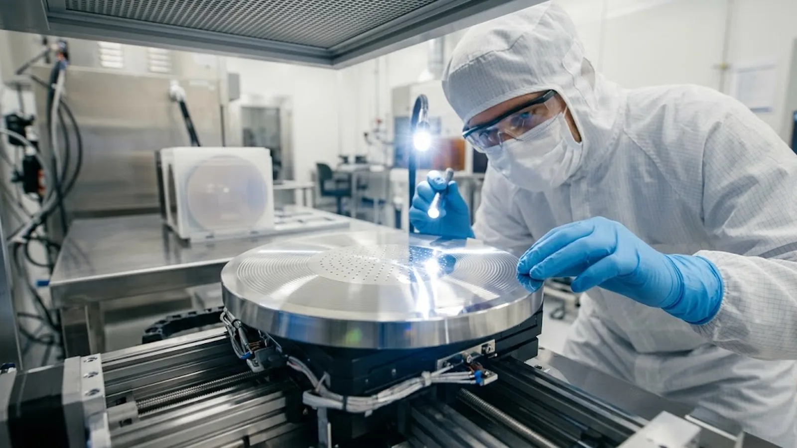
Bright, angled-light inspection of the chuck at defined intervals, with particle locations and counts recorded against a baseline.
TECHNOLOGY / SUBSTRATE HANDLING
A vacuum chuck holds the substrate for maskless exposure, but it is also the most common reservoir of particles that ruin focus, create defects and migrate into the optics. This guide explains where chuck particles come from, how they affect lithography results, and a practical cleaning, inspection and handling routine that keeps vacuum chucks production-clean.
Published
DIRECT ANSWER
A vacuum chuck in maskless lithography accumulates particles from substrate back sides, edge fragments, resist flakes and vacuum-line debris. Because the chuck sits millimeters below the exposed surface, particles on the chuck disturb substrate seating and flatness, appear as focus errors and feature distortions directly over the affected area, and can transfer to the front side of the next substrate placed on the stage. Particle control is therefore a scheduled maintenance task, not a reaction to visible defects.
A workable routine has four parts: inspect the chuck surface under bright angled light at every substrate change; clean with lint-free wipes and the approved solvent only, wiping in one direction from center to edge; keep the vacuum lines, seals and grooves as clean as the flat surface; and log inspection results so a rising particle trend is caught before it becomes a defect trend on patterned devices.
ENGINEERING CONTEXT
Maskless workflows change substrates frequently, and every change is a chance for particles to land on the chuck. Resist overhang from dicing, backside dust from carriers and wafer boxes, fragments from cleaved samples and debris drawn back through the vacuum ports all settle on a surface that is rarely inspected until something goes wrong. The failure mode is deceptive: a single particle under the substrate tilts it locally, so the autofocus pulls, one corner of the exposure blurs, and the operator blames resist or dose—while the real cause sits hidden on the chuck below. By the time defects appear on the pattern, weeks of samples may carry subtle focus degradation, and the vacuum lines have usually become a recontamination source that defeats surface cleaning alone.
Discuss your requirement ↗CRITICAL REQUIREMENTS
Bright, angled-light inspection of the chuck at defined intervals, with particle locations and counts recorded against a baseline.
Lint-free wipes, cleanroom swabs and solvents matched to the chuck material and seal chemistry, applied with a documented procedure.
Grooves, ports, filters and seals included in the cleaning routine, since backstreaming debris recontaminates a cleaned surface within days.
Backside cleanliness requirements for incoming substrates and carriers, so the chuck is not cleaned by the substrates placed on it.
BUYER MATRIX
Give every shortlisted supplier the same process definition and request configuration-specific proof.
| Approach | Method | Strengths | Watch-outs |
|---|---|---|---|
| Dry nitrogen blow-off | Filtered nitrogen across the surface before loading | Fast; safe for daily use | Does not remove adhered films or particles in grooves |
| Solvent wipe | Lint-free wipe with approved IPA or matched solvent, center-to-edge strokes | Removes most films and loose particles | Wrong solvent or wipe can shed fibers or attack seals |
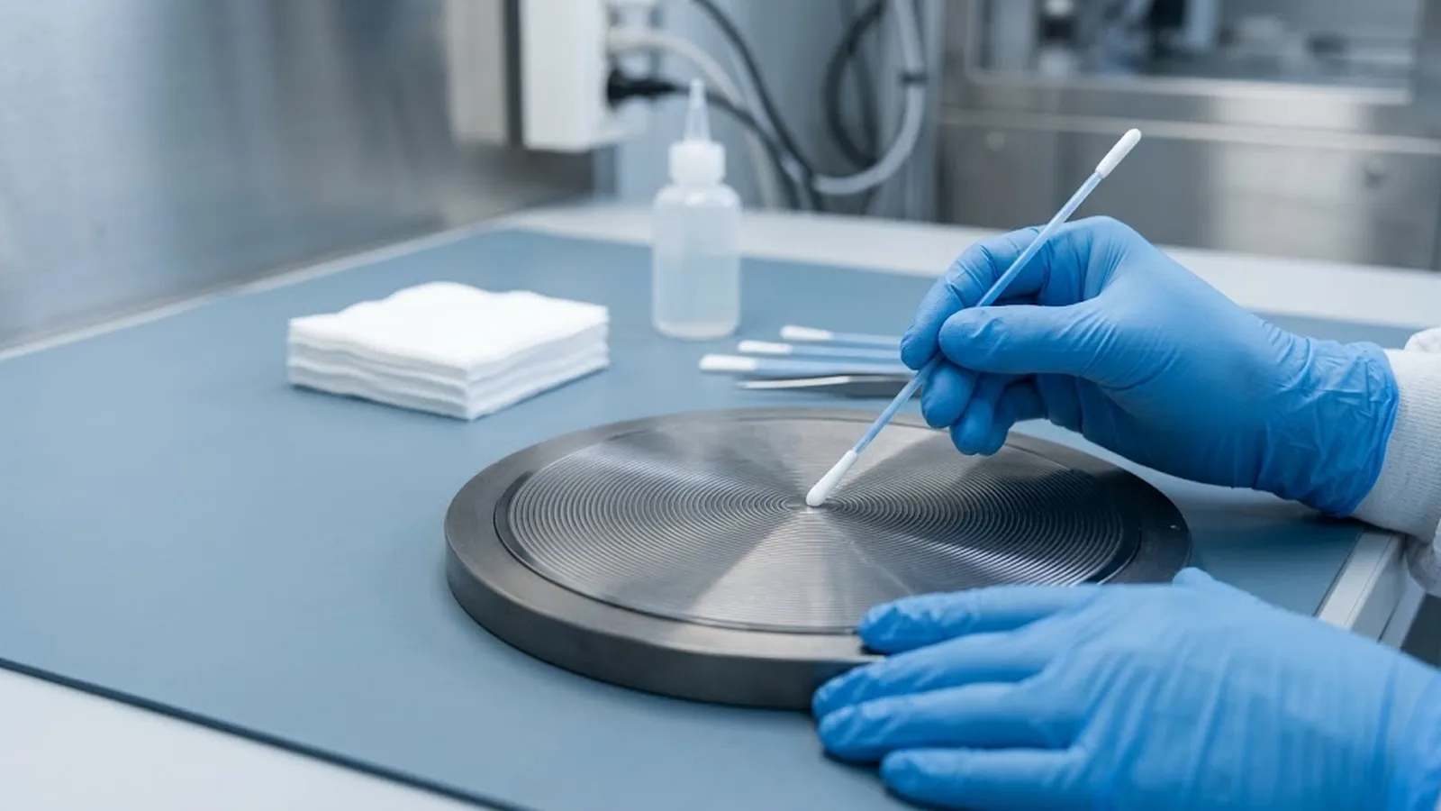
| Swab and groove cleaning | Cleanroom swabs on grooves, ports and seal lines | Clears the recontamination reservoirs | Time-consuming; needs care around seal edges |
| Wet bench or ultrasonic | Chuck removed and cleaned off-tool | Deepest clean; restores heavily contaminated chucks | Requires removal and re-qualification of seating and vacuum |
The contamination sources are predictable and mostly process-generated. Substrate back sides carry dust from storage boxes, carriers and dicing operations; each loading deposits a fraction of it on the chuck. Resist films flake from sample edges, especially after multiple exposures or aggressive development. Cleaved or snapped substrates shed glass and silicon fragments. Finally, the vacuum system itself contributes: unfiltered ports, aging seals and pump-line debris can backstream particles onto the surface exactly where suction pulls them.
The chuck's own geometry concentrates the problem. Vacuum grooves and channels are ideal particle traps, and the areas between grooves are precisely where the substrate must seat flat for focus and exposure uniformity. A particle that seems trivial by area can dominate the local gap between substrate and chuck, translating into a seating error that the autofocus must chase or fail against.
The primary mechanism is seating. A particle under the substrate creates a local wedge, so the exposed surface is tilted or bowed over the affected region. In maskless systems with autofocus, the focus servo may track the tilt and introduce stitching artifacts as focus changes across the pattern; without compensation, the affected area simply exposes out of focus, with widened lines and rounded corners. Because the particle position is fixed on the chuck, similar defects repeat at corresponding substrate locations across successive samples, which is the classic signature that distinguishes chuck contamination from random handling defects.
Front-side transfer is the secondary mechanism. Particles on the chuck can lift onto the back side of the next substrate, migrate during handling, and end up on the patterned face. In addition, debris in the vacuum path degrades holding force unevenly; a substrate that is not fully clamped can shift microscopically during stage moves, producing overlay errors that look like alignment or stage faults. All three paths cost far more in rework than the inspection routine that prevents them.
Inspect the chuck surface under bright, angled light at every substrate change for small tools, or at defined intervals for higher-throughput workflows. Angled light makes particles and films visible that flat illumination hides. Record what is found: count, size class and location. A stable low count with occasional outliers is normal; a rising trend across days means an active source, usually packaging, a failing seal or a dirty vacuum line, and surface cleaning alone will not stop it.
Clean with materials matched to the chuck: lint-free wipes dampened with the approved solvent, wiped in single strokes from center to edge, never circular scrubbing that redistributes debris. Grooves, ports and seal lines get cleanroom swabs on the same schedule, because they are the reservoir that recontaminates the flat. Where the chuck can be removed, a periodic off-tool deep clean with re-qualification of seating and vacuum performance closes the loop. Never use compressed shop air, brushes or unfiltered nitrogen; each adds particles faster than it removes them.
The durable solution is upstream discipline. Specify backside cleanliness for incoming substrates and keep carriers and boxes as clean as the tool itself. Dedicate handling tools to the lithography station. Include the vacuum path—filters, seals, pump line—in the maintenance calendar, not only the visible surface. And log everything: inspection counts, cleaning dates, and defect maps from patterned devices, so the correlation becomes visible and maintenance can be justified by data.
For laboratories running maskless lithography on sensitive or small samples, SENFU includes chuck and stage cleaning guidance in system documentation and can review the handling and maintenance workflow as part of installation or application support. A chuck that is inspected on schedule, cleaned with the right materials and fed clean substrates stays effectively invisible to the process—which is exactly what a chuck should be.
CONCLUSION
Vacuum chuck contamination is a quiet contributor to focus errors, repeating defects and overlay drift in maskless lithography. The particles come from predictable sources—substrate back sides, edge fragments and the vacuum path itself—and the failure signatures are distinctive once you know to look for them.
Put inspection under angled light on a schedule, clean the flat, the grooves and the vacuum path with matched materials, and require backside-clean substrates upstream. With those habits, chuck-related defects move from recurring mystery to scheduled, logged maintenance.
EVIDENCE CHECKLIST
FAQ
At every substrate change for small-sample R&D tools, or on a defined interval for higher-throughput workflows. The frequency should be set from the inspection log: a stable particle count justifies the interval, while a rising trend calls for shorter intervals and a source investigation.
Because the particle causing them is fixed on the chuck. A fixed particle creates the same seating disturbance each time, so similar focus or feature defects recur at corresponding substrate locations. This repeating signature distinguishes chuck contamination from random handling or process defects.
No. Shop air and unregulated blow-off guns add oil, water and particles and can drive debris into the vacuum grooves. Use filtered nitrogen for loose dust and lint-free wipes or swabs with the approved solvent for adhered contamination.
Inspect the vacuum grooves, ports, seals and pump line, which recontaminate the surface and can reduce holding force unevenly. Also verify substrate backside cleanliness and carrier condition, since a clean chuck can be recontaminated by the first substrate loaded onto it.
Not always, but it always risks it. A small particle under the substrate edge may have little optical effect, while the same particle in the pattern area causes local seating error and out-of-focus exposure. Since particle position is not controlled, the safe practice is to keep the chuck clean rather than gamble on where particles land.
AUTHORITATIVE SOURCES
TECHNICAL REVIEW
Send the application, critical parameters and any drawing or process information available.
Discuss your application ↗