Optical Encoders in Vacuum Environments: Selection, Outgassing, Thermal Behavior, and Operational Practice
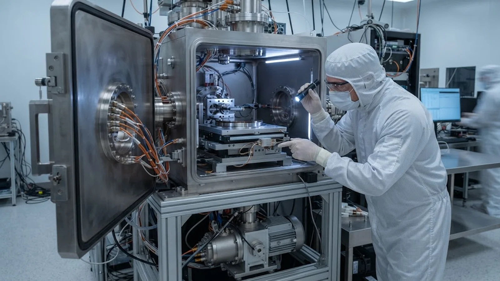
Running an optical encoder inside a vacuum chamber changes the physics of the measurement: convection disappears, materials outgas, bakeout cycles stress every polymer, and a fault found after chamber pump-down costs days. This guide covers what vacuum does to encoder optics and electronics, how to select and qualify a vacuum-rated installation, the thermal and signal effects to expect, and the operating practices that keep position feedback trustworthy between chamber openings.
Published
DIRECT ANSWER
What should a buyer prioritize?
An optical encoder can operate in vacuum, but only if the installation is designed for it, because vacuum removes the two things a standard encoder quietly relies on: air for convective cooling and cleanliness, and an atmosphere that suppresses outgassing. In vacuum, readhead electronics run hotter because heat leaves only by conduction, polymers release volatiles that can contaminate optical surfaces across the whole chamber, and every bakeout cycle ages cables, adhesives, and connector insulation. A conventional encoder dropped into a chamber frequently works at first and then degrades in ways that look like random signal drift, rising jitter, or contamination films appearing on windows and mirrors weeks later.
The working approach is to select a vacuum-rated encoder with documented materials and outgassing data, route all outgassing-bearing polymers deliberately and keep their total mass low, conduct readhead heat out through metal rather than air, plan cabling and feedthroughs as part of the chamber design rather than an afterthought, and qualify the installation with pump-down, bakeout, and signal-baseline measurements so that any later drift can be compared against a known reference. For e-beam lithography and other charged-particle tools, encoder feedback inside the chamber is often the only way to hold stage position once the beam is on, which makes this qualification part of the system specification, not a detail.
ENGINEERING CONTEXT
The decision starts with the real constraint.
Vacuum encoder problems are diagnosed late because the evidence only appears under vacuum, and the chamber is usually the most expensive machine-time in the lab. A readhead that meets every specification on the bench can show fine quadrature and clean Lissajous figures at atmosphere, then behave differently after pump-down as its electronics warm above their convection-cooled operating point and its PCB laminate or conformal coating begins to outgas. The classic failure pattern is a signal baseline that drifts during the first hours at high vacuum, distortion terms that grow with bakeout cycles, or a chamber that stops reaching its base pressure after an encoder retrofit because someone added fifty grams of unplanned polymer inside. Teams also discover that 'vacuum compatible' is not a single claim: a product rated for rough vacuum at moderate temperature may be entirely wrong for a 10⁻⁷ mbar e-beam chamber that bakes at 120 °C. Because every service visit means venting, purging, and re-pumping, the cost of an under-specified choice is not a replacement part but days of lost tool availability and a contamination risk to every surface inside the chamber.
State the operating pressure range, bakeout temperature, and radiation environment in writing, and require the encoder vendor to confirm material compatibility and rated performance for exactly those conditions—not a generic vacuum-compatible label.
02
Outgassing data for everything inside the chamber
Every polymer, adhesive, cable jacket, and PCB finish inside the chamber contributes gas load. Collect outgassing data (total mass loss and collected volatile condensable materials figures) for each item and keep the in-chamber polymer mass as low as the design allows.
03
Conduction path for readhead heat
With no air for convection, readhead dissipation must leave through its mounting into the chamber body. Specify a solid metal thermal path, verify readhead temperature rise by measurement at final pressure, and derate electronics for the resulting operating temperature.
04
Cabling and feedthrough designed with the chamber
Cable outgassing, flex life under bakeout, triboelectric noise, and feedthrough pinout belong in the chamber design from the start. Route encoder cabling away from high-voltage and electron-optical systems and follow the same grounding discipline used for precision signal chains.
BUYER MATRIX
Compare evidence, not feature labels.
Give every shortlisted supplier the same process definition and request configuration-specific proof.
Position feedback architectures for vacuum stages compared
Aspect
Standard encoder outside, motion through a window
Vacuum-rated encoder inside the chamber
Readhead inside with all-metal scale and minimized polymers
Measurement quality
Optical access through a window limits aperture and adds refraction and window drift effects; resolution achievable but Abbe and viewing geometry are constrained
Full measurement of the moving stage with no window compromise, but the entire encoder becomes a gas-load and heat source inside the chamber
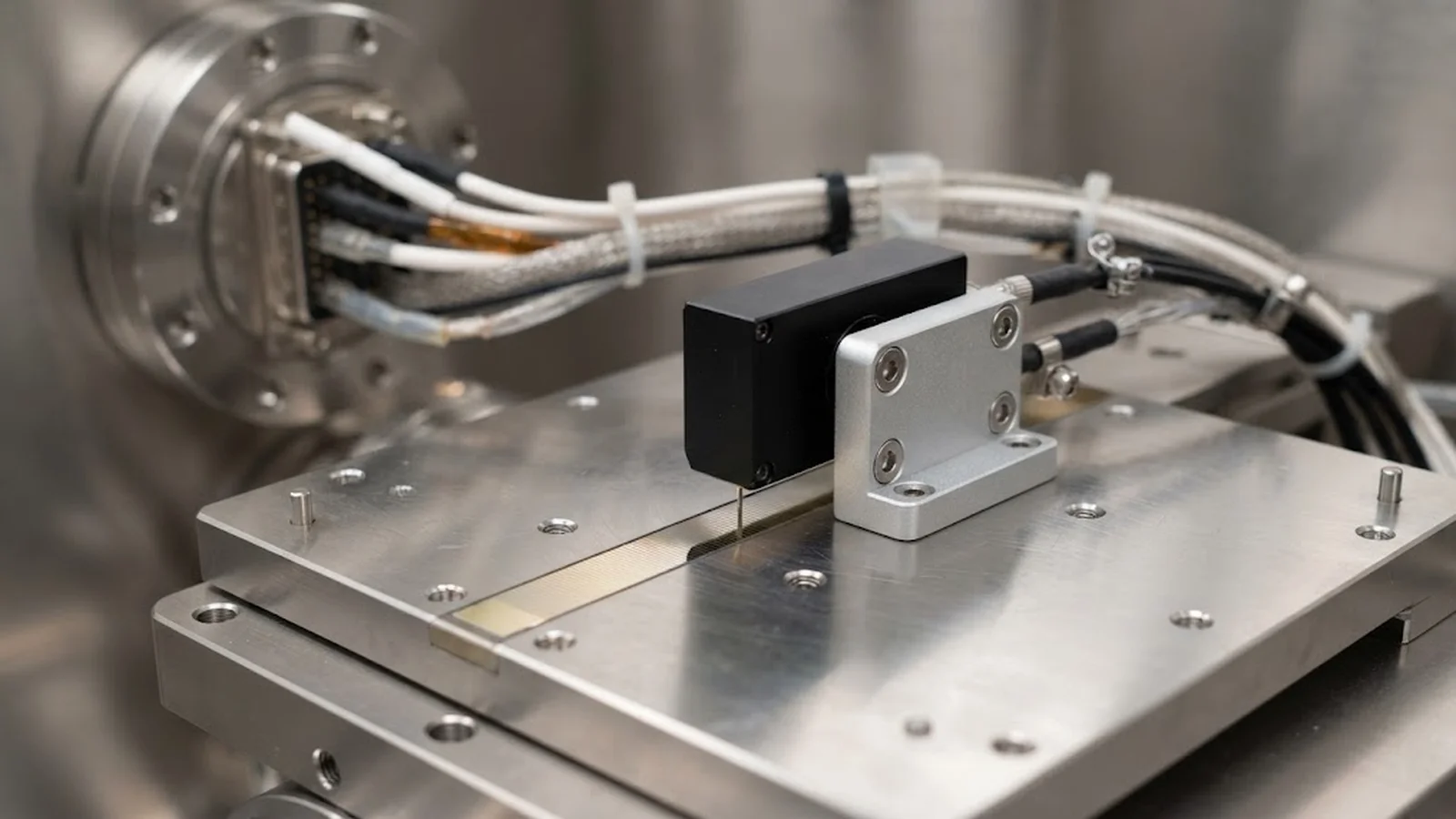
Direct measurement with the smallest practical in-vacuum footprint; requires disciplined material selection and conduction cooling
Contamination and gas load
Nothing inside except the scale, so gas load is minimal; window must stay clean, which in dirty processes is its own failure mode
Highest in-chamber polymer and electronics mass; outgassing must be budgeted and bakeout tolerated by every component
Moderate gas load, dominated by the readhead itself; adhesives and jacketing replaced with metal and PTFE or polyimide where possible
Service and failure behavior
Encoder serviceable without venting the chamber, but the window and external geometry set a ceiling on performance
Any service requires venting and re-pumping the chamber; failures discovered after bakeout are expensive
Same service constraint as any in-vacuum solution; mitigated by conservative derating and long-life LED and electronics choices
Best use
Rough and medium vacuum stages, clean processes, retrofits where chamber openings must be avoided
Medium vacuum stages with generous pumping and modest bakeout; common in wafer handling
High vacuum and UHV research stages, e-beam lithography and surface science tools where direct metrology is mandatory
What vacuum actually changes in an optical encoder
An optical encoder is a self-contained optical instrument, and vacuum touches every subsystem of it. The illumination LED loses convective cooling, so its junction temperature rises and its lifetime curve steepens; the readhead amplifier chain runs hotter, which shifts DC offsets and raises noise; the scale and readhead, no longer bathed in moving air, settle to temperatures set purely by conduction through their mounts. None of these effects is exotic—each is ordinary electronics behavior with the cooling mechanism removed—but their combination explains why a bench-qualified encoder can show different amplitude, offset, and distortion figures at 10⁻⁶ mbar than it did in the lab.
The second change is contamination physics. At atmospheric pressure, volatiles released by plastics are swept away by air movement; in vacuum they travel in straight lines and stick to the first cold surface they meet, which is frequently an optical surface. An outgassing cable jacket or a non-vacuum-grade conformal coating can film the scale, the readhead window, or neighboring optics anywhere in the chamber. The degradation is cumulative and directional—line-of-sight contamination maps can show one half of a scale dirtier than the other—and it is invisible until signals degrade. This makes the total polymer mass inside a chamber a system-level budget, exactly as it is for any other vacuum component.
Vacuum-rated encoder selection starts with a materials list, not a datasheet headline. Everything inside the chamber must be justified: cable jackets are typically replaced with PTFE or polyimide over PFA or similar, potting compounds and adhesives must have published outgassing data, and PCB finishes, connector insulators, and any conformal coating need the same review. The standard references are the familiar aerospace screening figures—total mass loss below one percent and collected volatile condensable materials below about 0.1 percent—which are screening criteria rather than guarantees, but they give the chamber designer a defensible basis for the gas-load budget. Unscreened additions, even small ones like a label or a cable tie, have measurably extended pump-down times in real systems.
Bakeout is the second discipline. Chambers are baked to accelerate outgassing and reach base pressure, and the bakeout temperature becomes the survival requirement for every encoder component: solder joints, laminates, LED encapsulants, magnet materials, and adhesives must all tolerate the full bake cycle, sometimes repeatedly over the tool's life. Note that this is close to the inverse of the sealing problem in atmospheric encoders: an IP-rated design tries to keep the environment out with gaskets and sealed housings, whereas a vacuum design must let trapped volatiles out quickly rather than trap them in blind cavities or sealed pockets that vent slowly for weeks. Reviewing the sealing logic against vacuum requirements is a useful exercise because it exposes every cavity and gasket in a standard readhead that would otherwise become a slow gas source.
Thermal behavior and signal integrity under vacuum
Thermally, a vacuum encoder installation must be designed like a conduction-cooled circuit board. The readhead mount is simultaneously its mechanical reference and its heat sink, so mount material, contact area, and joint quality directly set readhead temperature; a stainless bracket that is convenient mechanically may leave electronics tens of degrees hotter than an aluminum one. The practical sequence is to calculate readhead dissipation, verify the temperature rise by measurement at base pressure under the real motion profile, and then confirm that the measured operating point sits inside the vendor's rated range with margin for bakeout and duty-cycle peaks. Signal parameters shift with temperature in the same directions as at atmosphere—DC offsets and distortion terms drift, amplitude changes slightly—so the reference values recorded on the bench become the baseline for interpreting in-vacuum measurements.
Signal integrity in vacuum is dominated by cabling. Long cable runs to external electronics cross the feedthrough where connector quality and insulation materials matter, and triboelectric noise from cable motion, usually a minor term at atmosphere, becomes significant when stages move continuously in e-beam systems. Routing must keep encoder cabling physically separated from high-voltage electron-optical supplies and deflection systems inside the chamber, and the grounding architecture must be defined once for the whole chamber rather than improvised per instrument. The rules that apply to precision encoder signal chains at atmosphere carry over unchanged; vacuum mainly removes the margin for sloppy routing, because re-routing a cable inside a qualified chamber means venting the machine.
Measure readhead temperature rise at base pressure, not at atmosphere, before releasing the installation to operation
Record quadrature balance, offsets, amplitude, and distortion at atmosphere, after pump-down, and after bakeout as the signal baseline
Keep encoder cabling separated from electron-optical and high-voltage harnesses with a documented chamber grounding scheme
Derate LED lifetime for the measured in-vacuum junction temperature and plan illumination service around it
Qualification for a vacuum encoder installation should follow the same structure as the chamber's own acceptance: a documented pump-down test that records base pressure and pump-down time against the pre-installation reference, a bakeout survival test at the specified temperature with signal verification after cooldown, and a dynamic signal test that exercises the stage through its real motion profile while logging position noise and velocity stability. Comparing the signal baseline across these states—before and after pump-down, before and after bake—converts vague confidence into numbers that any later anomaly can be judged against. Chambers used for e-beam lithography add one more check: confirmation that switching the beam and its supplies on does not couple into the encoder signals, because the most convenient ground path for interference is often the newly installed feedback cable.
Operationally, the goal is to avoid opening the chamber. That means trend monitoring on the signals that drift predictably—offsets, amplitude, distortion—so illumination aging or contamination is caught while it is still a scheduled intervention rather than a failure, and it means treating any in-chamber modification, however small, as a gas-load event that goes through the same materials review as the original installation. Facilities that maintain a written materials list and a signal baseline spend their vacuum budget on experiments; facilities that do not spend it on venting cycles. When a stage is being selected or upgraded, the application requirements for vacuum motion spell out the pressure, bakeout, and integration evidence to demand from any feedback supplier.
Vacuum does not create new physics for an optical encoder; it removes the assumptions that standard installations rely on. Without convection, heat must be conducted out deliberately; without air, outgassed volatiles land on optics; without cheap chamber access, every under-specified component becomes days of downtime instead of an afternoon swap. The failures seen in the field are almost all traceable to materials, thermal paths, or cabling decisions made before the first pump-down.
The discipline is compact: select a vacuum-rated encoder with documented materials and pressure-bakeout ratings, keep the in-chamber polymer mass inside a written budget, conduct readhead heat through metal and verify the temperature at base pressure, route and ground cabling as part of the chamber design, and record a signal baseline across atmosphere, vacuum, and bakeout states. An installation qualified this way holds its performance for years of pump cycles—and when drift does appear, the baseline tells you within minutes whether it is the encoder or the environment.
Vendor statement of rated pressure range, bakeout temperature, and in-vacuum performance for the exact encoder model and cable type
Outgassing data (total mass loss and collected volatile condensable materials) for every polymer-bearing component installed inside the chamber
Readhead temperature rise measured at base pressure under the real duty cycle, with electronics derating confirmed against it
Signal baseline recorded at atmosphere, after pump-down, and after bakeout: quadrature balance, DC offsets, distortion, and amplitude compared between states
Chamber base pressure and pump-down time before and after encoder installation, demonstrating the added gas load is within the chamber budget
FAQ
Questions engineers ask before selection.
Can a standard optical encoder be used inside a vacuum chamber?
Only at rough vacuum and moderate temperature, and only after a materials review. Standard cable jackets, adhesives, and coatings outgas measurably, standard readheads run hotter without convection, and none of it is rated for bakeout. For high vacuum, UHV, or any chamber that bakes, use a vacuum-rated model with documented outgassing data and a conduction-cooled mounting design.
What outgassing limits should encoder components meet?
The common screening criteria are total mass loss below 1 percent and collected volatile condensable materials below 0.1 percent, per the standard aerospace vacuum screening tests. These are screening values, not performance guarantees: the chamber designer should still sum the actual polymer mass installed and verify that pump-down time and base pressure stay within the chamber's budget after installation.
Why does an encoder signal change after pump-down even though nothing moved?
Mostly temperature. With no convective cooling, readhead electronics rise to a higher operating point, shifting DC offsets and distortion terms and slightly changing amplitude. These shifts are normally small and stable once thermal equilibrium is reached, which is why the signal baseline should be recorded after pump-down and after bakeout, not only at atmosphere.
How does bakeout affect encoder selection?
Bakeout temperature becomes a survival requirement for every encoder component: solder joints, PCB laminates, LED encapsulants, magnets, and adhesives must tolerate the full bake cycle repeatedly over the tool's life. Specify the maximum bakeout temperature when selecting the encoder, and verify signal parameters after the first bake rather than assuming survival.
How is contamination from encoder outgassing detected?
Indirectly first, through signal degradation—falling amplitude, growing distortion, rising jitter—plus chamber symptoms such as extended pump-down times. Line-of-sight contamination maps inside the chamber often show the source's direction. The reliable method is prevention: outgassing data for every in-chamber component, a written polymer budget, and trend monitoring of signal parameters against the recorded baseline.