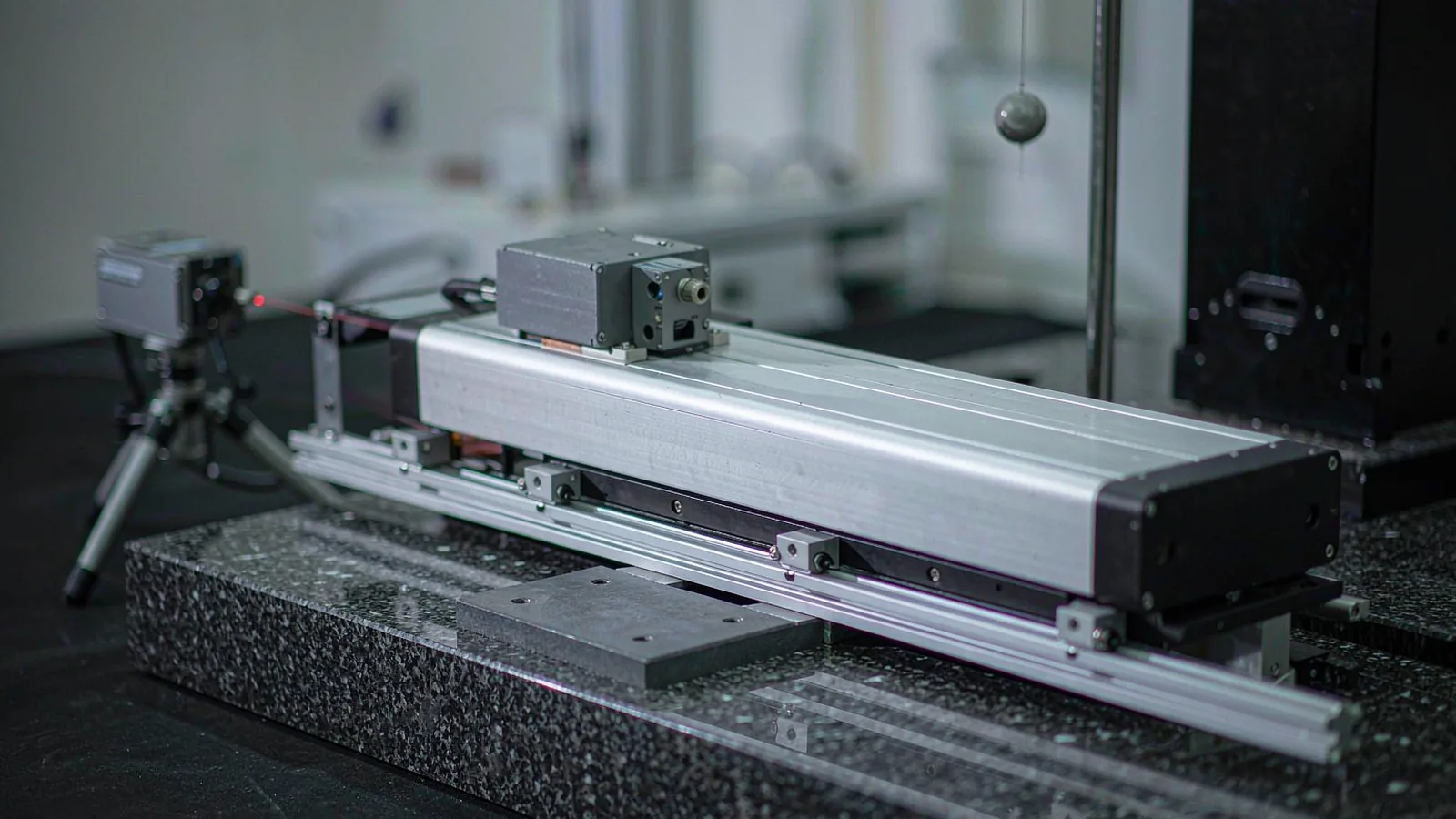
Optical Encoder vs Laser Interferometer Feedback for Precision Stages: Choosing the Position Signal and Designing Hybrid Architectures
Optical encoders and laser interferometers both deliver nanometer-class position feedback, but they measure against different references and fail in different ways. This guide compares scale-based and interferometer-based feedback on resolution, bandwidth, environment sensitivity, travel range, and cost, and explains when a hybrid architecture—with cross-calibration between the two—outperforms either technology alone.
Published
DIRECT ANSWER
What should a buyer prioritize?
An optical encoder measures stage position relative to a scale mounted on the machine, while a laser interferometer measures displacement relative to a stabilized laser wavelength—an external, traceable reference. The encoder is the better servo feedback: high bandwidth, tolerant of dust and vibration, affordable, and permanently installed. The interferometer is the better metrology instrument: sub-nanometer resolution, traceable to the wavelength standard, non-contact, and able to measure at the point of interest—but sensitive to air refractive index, sensitive to alignment, and impractical as an always-on industrial feedback for most machines.
The practical selection rule is to define what the position number must be referenced to. If the process is defined relative to the machine (as in most patterning, inspection, and assembly), a calibrated optical encoder with an error map gives the best accuracy per cost and the fastest control loop. If the position must be traceable to the SI meter, or the measurement must be independent of machine geometry drift, a laser interferometer is required. Many precision stages use both: the encoder closes the velocity and position loops at high bandwidth, while a periodic interferometer cross-calibration verifies and updates the encoder error map. Hybrid designs that feed both signals into the controller combine the encoder's bandwidth with the interferometer's absolute accuracy, at the cost of integration complexity.
ENGINEERING CONTEXT
The decision starts with the real constraint.
The mistake that recurs in stage procurement is comparing the two technologies on headline resolution and concluding that the interferometer is simply better. The comparison collapses in both directions once the system context enters. An interferometer specified at 0.1 nm resolution on a datasheet arrives on a machine where air temperature drifts a fraction of a degree, refractive-index compensation is approximate, the measurement beam is offset from the moving point by an Abbe arm, and dead-path error shifts the zero—so the achieved accuracy can be an order of magnitude worse than the resolution suggests. Conversely, an encoder quoted at ±100 nm per meter of scale accuracy is dismissed as too coarse, although that figure applies along the whole travel, the error map is highly repeatable, the signal survives coolant mist and vibration that would break an interferometer beam, and the loop bandwidth is ten times higher. Teams then discover the real problem only after integration: the interferometer feedback cannot close a velocity loop through its sampling latency and signal drop-outs, or the encoder feedback cannot be traced to any standard during audit. The failure is architectural, not component quality—and it is avoidable by deciding the reference question before the purchase order.
Decide explicitly whether position must be relative to the machine structure (process-defined) or traceable to the wavelength standard (metrology-defined). This single decision eliminates most of the selection space before datasheets are opened.
02
Dynamic requirements quantified
State the velocity profile, acceleration, and required servo bandwidth. Interferometer signal processing and sampling impose latency and drop-out constraints; encoder bandwidth supports fast loops. The feedback must close the loop the stage needs.
03
Environment characterized
Measure the temperature stability, gradients, airflow, vibration, and contamination the feedback will actually see. Air refractive index and dead path dominate interferometer error in ordinary rooms; scale CTE and mounting dominate encoder error.
04
Accuracy budget across the whole travel
Compare error over full travel, not at a point: encoder scale accuracy and error-map residuals versus interferometer cumulative error from compensation, Abbe offset, and dead path. Include bidirectional behavior and long-term drift.
05
Integration and service plan
Confirm mechanical envelope for scale or beam path, alignment tolerance and retention, cable or beam routing in motion, and who performs periodic calibration. A feedback that cannot be maintained in situ will drift out of specification regardless of its datasheet.
BUYER MATRIX
Compare evidence, not feature labels.
Give every shortlisted supplier the same process definition and request configuration-specific proof.
Optical encoder vs laser interferometer as precision stage position feedback
Aspect
Optical encoder (scale + readhead)
Laser interferometer
Hybrid (encoder + interferometer)
Measurement reference
Scale fixed to the machine structure; position is machine-relative
Stabilized laser wavelength; position is traceable to the SI meter
Encoder for machine-relative servo control; interferometer as periodic or continuous reference
Resolution and noise floor
Nanometer-class after interpolation; noise dominated by signal quality and electronics
Sub-nanometer; limited in practice by air turbulence and vibration of the measurement path
Interferometer-grade resolution available for verification; encoder noise floor during motion
Bandwidth and dynamics
High: supports fast velocity and position loops, acceleration in g-class
Moderate: processing latency and signal drop-out limit loop bandwidth and maximum velocity
Robust to dust, mist, and vibration when sealed; scale temperature and CTE drive accuracy
Sensitive to air refractive index (temperature, pressure, humidity, airflow, CO2), turbulence, and beam obstruction
Encoder tolerates the environment between calibrations; interferometer used when the room is stable
Travel and installation
Travel limited by scale length and splicing practice; compact readhead, minimal envelope
Very long ranges possible; requires clear beam path, stable optics, and alignment maintenance
Encoder covers production travel and duty; interferometer beam retained on a metrology-grade axis or used at a calibration station
Cost and ownership
Low to moderate; installed permanently, serviced like any machine component
High instrument cost; alignment upkeep, compensation management, and operator training
Highest system cost; justified where traceability and bandwidth are both hard requirements
Two feedbacks, two references: what each technology actually measures
An optical encoder is a self-contained measuring system on the machine. A graduated scale—glass, steel, or Invar—is mounted along the axis of travel, and a readhead riding on the moving carriage reads the graduations optically, producing interpolated position at high rate. Everything the encoder reports is relative to the scale, and the scale is part of the machine: it expands and contracts with its substrate temperature, it carries whatever geometry errors were locked in at manufacture, and it measures at the readhead location rather than at the workpiece. This is not a weakness; it is a design intent. Most production processes—patterning, dispensing, inspection, assembly—are defined relative to the machine's own datum structure, so a feedback that is rigidly tied to that structure tracks the errors the process actually cares about.
A laser interferometer measures displacement differently: it compares the phase of a measurement beam reflected from the moving stage against a reference beam, counting wavelengths of a frequency-stabilized laser. The reference is the wavelength itself—traceable to the SI definition of the meter under stated conditions—which is why interferometers anchor calibration chains and acceptance tests. But the beam travels through air, and the number of wavelengths between the optics changes with the refractive index of that air: roughly one part per million per degree Celsius, with additional sensitivity to pressure, humidity, and even CO2 content. The measurement is also line-of-sight: the beam must have an unobstructed path, the retroreflector must stay aligned over travel, and the measurement point is where the mirror is, not where the workpiece is. Each of these properties shapes where the technology belongs.
Where the encoder wins: dynamics, robustness, and machine-relative accuracy
As servo feedback, the encoder is the default for good reasons. Its bandwidth is high enough to close velocity loops at hundreds of hertz and position loops at tens, which directly determines tracking error during motion and settle time at target. The signal does not require a clear optical path through the room; sealed encoder systems run in coolant mist, near motors, and under vibration that would scatter an interferometer beam or saturate its receiver. Installation is permanent and maintenance-light: once the scale and readhead are set and verified, the feedback behaves like a machine component, not like an instrument that needs re-alignment after every crash scare or maintenance intervention.
Accuracy is the area where the honest comparison must be made carefully. A quality encoder scale carries a stated accuracy grade—commonly from a few micrometers down to well under a hundred nanometers per meter depending on class—and the residual error after an error map is applied is small and highly repeatable, because the scale graduations do not change. The dominant long-term variable is temperature: the scale's coefficient of thermal expansion translates any scale temperature change into position error, which is why scale material selection and thermal management matter more than nominal grade for sub-micron machines. For an environment with modest temperature control, a mapped encoder on a low-CTE scale delivers machine-relative accuracy that most processes cannot exploit further, at a fraction of the cost of interferometer feedback.
Where the interferometer wins: traceability, non-contact range, and measuring the real point
The interferometer's decisive advantages appear in three situations. First, traceability: when a stage's accuracy must be stated against the SI meter—in calibration laboratories, metrology-grade machines, and supplier acceptance testing—the stabilized wavelength is the reference of record, and no encoder can substitute for it because the encoder itself needs calibration. Second, non-contact measurement over long travel: an interferometer measures without touching, over ranges from tens of millimeters to many meters, with no scale to splice and no readhead riding the carriage. Third, geometric completeness: a properly planned interferometer setup measures displacement at the functional point—using multiple axes and angular optics, it can capture the stage's six-degree-of-freedom error motion rather than the position at one embedded readhead.
The datasheet resolution must not be mistaken for achieved accuracy. Between the stabilized wavelength and the displayed position sit several error mechanisms that belong to the installation, not the instrument: dead-path error from any distance between the reference mirror plane and the stage's zero position, which magnifies refractive-index error even when the stage does not move; Abbe error from any lateral offset between the measurement beam and the point being compared; periodic error from optoelectronic nonlinearity; and turbulence along the beam path, which appears as noise that no compensation removes. Environmental compensation corrects the bulk refractive index using measured temperature, pressure, and humidity, but sensor placement errors and gradients leave residuals. These mechanisms are exactly why the interferometer delivers its rated accuracy in a controlled metrology lab and considerably less on a production floor—the measurement procedure and its error separation deserve the same rigor as the instrument choice.
The decision framework: reference, dynamics, environment, budget
A defensible selection follows four questions in order. First, reference: is position defined relative to the machine or traceable to the standard? If the process specification is written in machine coordinates—and it usually is—the encoder is architecturally correct and the interferometer is a calibration tool, not feedback. If results must be compared across machines, over years, or against a standard, interferometer feedback or at minimum interferometer-based periodic calibration enters the design. Second, dynamics: extract the motion profile and required bandwidth; an interferometer whose processing latency and drop-out behavior cannot support the velocity loop will force the stage to run on inner-loop feedback anyway, at which point the interferometer has become the calibrator regardless of the original intent.
Third, environment: measure the room, not the brochure. For the interferometer, the questions are temperature stability, gradients along the beam, airflow, and whether the beam path can stay clear in production; for the encoder, the questions are scale temperature range, gradients between scale and structure, and contamination class. Fourth, error budget and cost: place the feedback contribution into the stage's total error budget alongside mechanics, drives, and thermal design—the feedback only needs to be accurate relative to the whole budget, and over-provisioning it usually means under-provisioning something that matters more. Applied honestly, this framework sends most production stages to mapped encoders, most metrology and acceptance work to interferometers, and a specific, well-defined class of machines to hybrid designs.
Hybrid architectures: using both signals without doubling the errors
The most common hybrid is temporal: the encoder closes the high-bandwidth servo loops, and the interferometer enters as a slow correction or a periodic verification. In the periodic form—an encoder whose error map is refreshed by interferometer cross-calibration at defined intervals—the interferometer never runs in production; it lives in a calibration procedure that compares encoder position against wavelength-traceable displacement over travel and in both directions, and the differences update the compensation table. This captures scale drift, mounting shifts, and long-term wear, and it converts the encoder from a fixed component into a traceable one. The cross-calibration record, with its uncertainty and conditions, becomes the audit artifact that machine-relative feedback alone cannot provide.
The continuous hybrid feeds both signals into the controller: the encoder carries the dynamic loop while the interferometer provides a low-bandwidth absolute reference that the controller steers the encoder toward, exploiting the interferometer's drift-free accuracy without asking it to track fast motion. This architecture earns its complexity only on machines where both requirements are hard simultaneously—long-travel metrology stages, lithography-class platforms, and calibration artifacts—because it doubles the alignment, electronics, and failure modes, and its benefit collapses if the two measurement lines do not share the functional point closely enough for their difference to be meaningful. Signal-level consequences also deserve attention: whatever the mix, feedback noise and drop-outs propagate into velocity jitter and path follow error, and the combined feedback must be verified in motion, not only at rest.
Encoder versus interferometer is not a ranking but a reference decision. The optical encoder measures the machine against its own scale—fast, robust, economical, and exactly right when the process lives in machine coordinates. The laser interferometer measures displacement against a stabilized wavelength—traceable, non-contact, and unmatched for verification and metrology, but demanding in alignment, compensation, and environment. Most of the wrong purchases traced to feedback come from skipping that reference question and comparing resolution figures instead.
The working procedure is short: define what position must be referenced to, quantify the motion profile and bandwidth the loop must close, characterize the environment the feedback will actually see, and place the feedback error into the stage's total budget with its cost. Production stages land on calibrated, error-mapped encoders; traceability and acceptance work lands on interferometers; the machines that genuinely need both get a hybrid designed around shared measurement lines and a documented cross-calibration interval. Specified this way, the feedback stops being the stage's weakest link and becomes the quietest part of the error budget.
Encoder datasheet with scale accuracy grade over full travel, resolution after interpolation, maximum velocity, and CTE of the scale substrate
Interferometer specification with wavelength stability, resolution, maximum velocity and acceleration, and the compensation method for air refractive index
Environmental data for the installation: temperature range and stability, gradients, pressure and humidity variation, vibration spectrum
Error map or calibration certificate for the encoder scale, stating measurement uncertainty and the reference it is traceable to
Cross-calibration record comparing encoder position against interferometer measurement over travel, in both directions, at defined temperatures
Servo performance data: loop bandwidth, tracking error during the production motion profile, and positioning settle time with each feedback option
FAQ
Questions engineers ask before selection.
Is a laser interferometer always more accurate than an optical encoder?
Not on an installed machine. The interferometer's sub-nanometer resolution is referenced to a stabilized wavelength, but its achieved accuracy depends on air refractive-index compensation, dead-path error, Abbe offset, alignment, and turbulence—so on a production floor its real accuracy can be worse than a calibrated, error-mapped encoder that is mechanically referenced to the machine. The interferometer is more accurate when those error sources are controlled, which typically means a metrology-lab setting and a disciplined measurement procedure.
Can a laser interferometer be used as the primary servo feedback of a stage?
In some machines, yes—metrology stages and slow, high-accuracy axes run on interferometer feedback, sometimes with an internal encoder or tachometer carrying the fast inner loop. In general, interferometer signal processing latency, maximum velocity, and drop-out behavior limit loop bandwidth, so fast production stages use encoder feedback and reserve the interferometer for verification or slow correction. The motion profile decides this as much as the accuracy requirement does.
What is dead-path error and why does it matter?
Dead path is the distance between the interferometer reference mirror plane and the measurement retroreflector at the zero of stage travel. Any change in air refractive index along that idle distance shifts the measured position even when the stage has not moved, adding error proportional to the dead-path length and the index change. Minimizing dead path by placing optics close to the zero position, or applying dead-path correction with environmental data, is standard practice in serious interferometer measurements.
How often should an encoder be cross-calibrated against a laser interferometer?
The interval follows observed drift, not a fixed rule. A new machine or a new error map is verified after commissioning and then at increasing intervals—commonly quarterly in the first year—while the cross-calibration records show how much the encoder-to-interferometer difference moves with time, temperature cycling, and usage. When the difference is stable at a level well inside the accuracy budget, the interval can be extended; when it trends, the map is refreshed and the interval shortened. The records themselves are the traceability evidence for audits.
What does a hybrid encoder–interferometer architecture cost beyond the instruments themselves?
The visible costs are the interferometer optics, electronics, and a second measurement path on the machine. The less visible ones dominate: mechanical integration that keeps both measurement lines close to the functional point, controller integration for combining a high-bandwidth and a low-bandwidth signal, alignment retention through vibration and maintenance, and the operating procedure for cross-calibration. Hybrid designs are justified where bandwidth and traceability are both hard requirements; where only one is, a single feedback plus periodic calibration usually achieves the same result for a fraction of the complexity.